This thread has been locked.

If you have a related question, please click the "Ask a related question" button in the top right corner. The newly created question will be automatically linked to this question.

UCC28950: UCC 28950 reboot constantly

Part Number: UCC28950

Hello Team.

We are implementing a DC/DC power supply with the UCC28950 and with the following specifications:

  • VIN = 36 VDC
  • Vout = 170 VDC
  • operation Frequency = 100 kHz
  • output Power : 3 kW

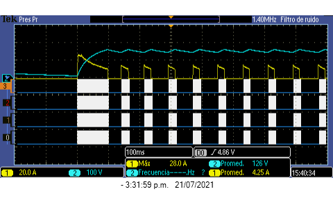
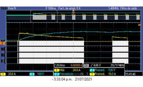
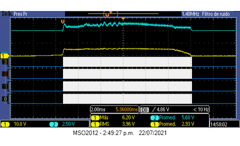
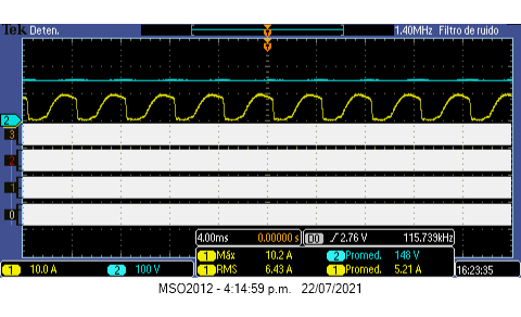
The problem is that the DC/DC converter output never stabilizes, when it starts, it gets to the desired voltage but immediately turns off. This sequence happens all time. 

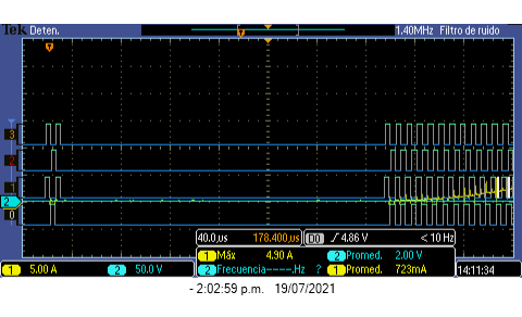
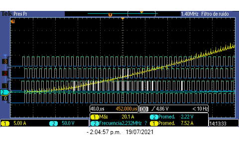
The following picture shows this operation.

The blue signal is the output voltage, the yellow signal is the input current. The white signals are the PWM.

Could you please tell me what could be happening and how to repair this fail?

  • Hi, Javier

    it looks UCC28950 enter burst mode. 

    I think there is no Synchronous rectification on secondary side since the output voltage is high。

    You can try to decrease resistor on TMIN pin to 10kohm, which can make the burst mode threshold at minimal value.

    Yunsheng

  • Thank you Yunsheng for your soon answer.

    You are right, I don't have Syncrhonous rectification on secundary side. I had the Tmin Resistor on 13 kOhm and I changed it to 10 kOhm but the response is similar. I am thinking that the problem could be the current sensor network. The following picture shows the input current (yellow signal) and of the sensor current signal (blue siignal). What do you thing about it? 

    Thank you

  • Hi, Javier

    Could you help to zoom in the first 10 switching cycle when OUTX is enable? please capture the CS/OUTA/OUTB pin voltage and input current in the sane waveform.

    It is better to share the schematic, please help to get it.

    Yunsheng

  • Hello Yunsheng

    I am sending the pictures of the current signals and the first swiching cycles.

    In the before pictures, blue signal is  CS voltage and yellow is the current signal.

    In this picture, the yellow signal is output current and blue is output voltage.

    Conversor_DC_DC_V1.pdf

    Thank you for your help

  • Hi, Javier

    I found several problems on the schematic, here is my comments, you can try to modified:

    1. SYNC should be left open circuit or tied to ground through a 1k resistor.

    2.If SRs are not used then OUTE, OUTF should be left open circuit and ADELEF tied to GND. The DCM pin should be tied to VREF.

    Yunsheng

  • Hi Yunsheng

    Thank you for your answer. We followed your instructions.

    1. We put a 1k resistor in the SYNC pin.

    2. The OUTE and OUTF pins are in open circuit.

    3. The ADELEF pin was tie to GND.

    4. The DCM was tie to VREF.

    After it, the converter has the same problem. The following are the pictures after this new configuration.
    We anex the new schematics.

    The yellow signal is the input current and the blue signal is output voltage.

    5707.Conversor_DC_DC_V1.pdf

    Thank you for your help

  • Hi, Javier

    I received similar issue from other customer,  it seems the VREF of UCC28950 is not stable which make VCOMP overshoot a lot. Could you help to get VREF/VCOMP/SS/OUTA/OUTD together?

    thanks 

    Yunsheng

  • Hi Yunsheng

    I am sending the new signals and we saw that the VREF was not stable, you were right. The following are the signals.

    The blue signal is VREF and the yellow signal is SS.

    The blue signal is VREF and the yellow signal is SS.

    Now: 

    The blue signals is VREF and yellow signal is VCOMP

    We put the capacitor closer to the VREF and our response was better. The following are the picture of our new response.

    The blue signal is the output voltage and the yellow signal is the output current. In this case, the PWM is not reb0oting but We don't understand why the current signal has this waveform and If we increase the load the DC-DC converter is rebooting again. The following picture shows it.

    Thank your for your help

  • Javier

    first of all, you need to confirm VREF is stable at all the load condition, otherwise it is normal to see the system unstable.

    regarding to new response, if VREF is stable, then the loop compensation is need to optimized, it is better to test gain/phase curve of feedback loop.

    anther important point is the layout, it is recommended to use 4 layers for UCC28950 and place ground plane under UCC28950, it is not possible to make UCC28950 stable with two layers PCB.

    Yunsheng