https://www.ti.com/lit/ds/symlink/ucc27714.pdf
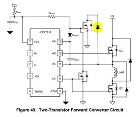
I want to use UCC27714 in a 2-switch flyback. Datasheet section 7.4.3 has fig 49 which shows an implementation for circuit to achieve this.
Section 7.4.3 mentions that 2 additional diodes and FETs required, while fig 49 only shows one additional diode.
Can you advise where the second additional diode is meant to go.
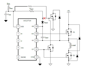
When I simulate this circuit I need to make Rboot>100ohm to stop VDD from effectively shorting or hitting UVLO. Power in the resistor is 12^2/100R=1.44W (average approx. 0.8W)
I'm assuming/hoping that if I put in the missing diode this wouldn't be as bad.
Can you advise where the other diode