This thread has been locked.

If you have a related question, please click the "Ask a related question" button in the top right corner. The newly created question will be automatically linked to this question.

TPS3808G01DBVEVM: TPS3808

Part Number: TPS3808G01DBVEVM
Other Parts Discussed in Thread: TPS3808-Q1, TPS3808, AMC1311

Hi,

In my circuit i have connected the reset output to the enable pin converter.

Condition is shown below,

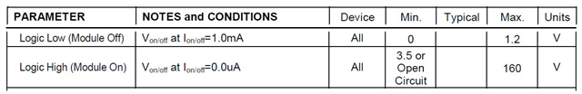
VDD = 5.1V, MRn = VDD, Gnd = 0V.

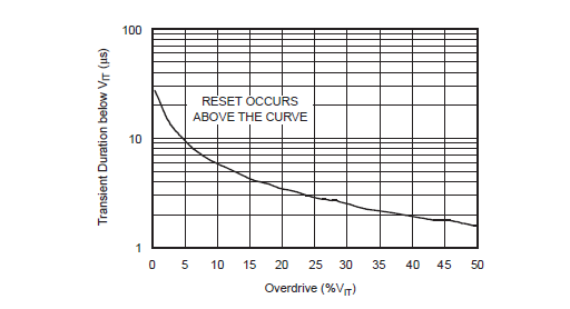
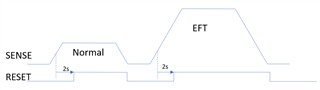
SENSE voltage < Vit reset get asserted = Disable 

SENSE voltage > Vit after time delay of 2s reset get deasserted = Enable.

In normal operation works good as per the above condition.

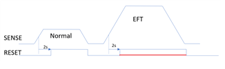
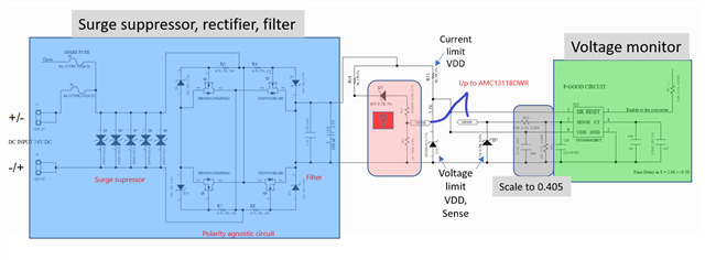
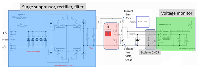
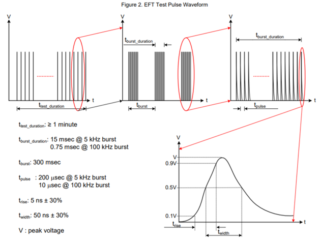
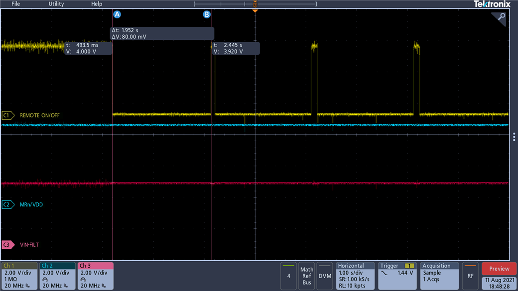
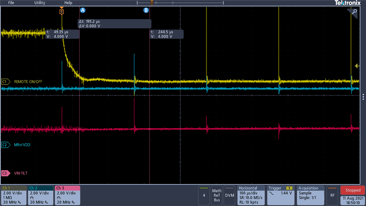
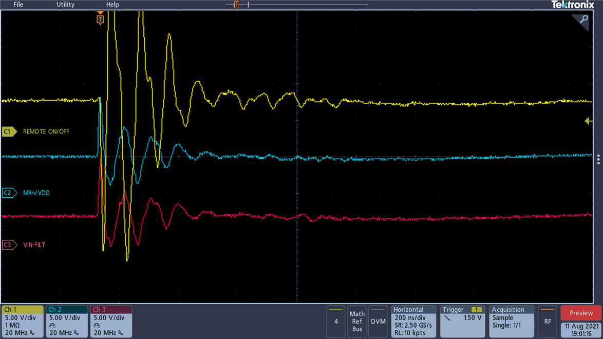
Problem: When EFT transient is applied across line to line, The converter is disable & resume to work after EFT duration of 60s. Circuit is posted in the image below,

There is set of transorbs right at the input of circuit (30KPA102CA) & 4.7V zener diode at the input of SENSE voltage Pin with 10nf bypass capacitor.

Possible solution to pass the EFT transient test suggestions.

Possible 

  • Hi Vijay,

    Can you provide more information regarding the TPS3808-Q1 and its output signal when an EFT occurs?

    Ben

  • Hi Ben,

    Thanks for the response.

    The exact partnumber used in the circuit - TPS3808G01DBVT (Adjustable Vit)

    Vit choosed for application is 0.54V

    Condition @ Normal

    Input voltage to the board = 74V which is scaled down to sense voltage (2.2V) > Vit (0.52V) after a time delay of 2s reset signal get deasserted.

    i.e., Since reset signal is connected to the enable pin of the converter, Reset deasserted = Enable for the converter.

    Condition @ EFT

    Input voltage to the board = 74V which is scaled down to sense voltage (2.2V) > Vit (0.52V), Reset asserted = Disable for the converter.

    Once EFT is done automatically it resumes to Reset deasserted = Enable for the converter.

    In the best possible way i had explained the problem. Expecting the possible solution.

    Thanks,
    VIJAY M

  • Sorry for missing this information.

    Asserted - High to Low,

    Deasserted - Low to High.

  • Hi Vijay,

    Is there a reason when the EFT transient is applied across line to line, the converter is disable & resume to work after EFT duration of 60s?  I guess I am a little confused with the EFT signal.  Without applying the EFT signal your application works fine.  When applying the EFT signal, the TPS3808 does not de-assert until 60s has passed.  Is my understanding correct?

    Ben 

  • Hi Ben,

    Your understanding is right.

    Normal condition works fine and when EFT signal is applied converter is disable for duration of 60s and resume to working condition after that.

    Vijay M

  • HI Vijay,

    Thanks for helping me understand your situation.  Would you have any scope photos on /MR, VDD, and SENSE?  What happens if capacitance was added to SENSE and VDD?  Can a pull up resistor be added to /MR pin?

    Ben

  • Hi Ben,

    Since this testing was done in the external lab didn't have chance to capture the scope photos, But measured the reset output through multimeter, It was supposed to be high but it was low when EFT is applied.

    Present circuit,

    Capacitance of 10nf & 0.1uf was connected at SENSE & VDD pin respectively.

    /MR pin directly connected to the VDD, How it will improve if i connect it through pull-up resistor??

    Vijay M

  • Hi Ben,

    Graph shown below in the datasheet of the TPS3808.


    IF (Sense voltage > Vit) greater by some % i.e., Overdrive(%Vit) = 300

    & with duration of time = EFT signal (IEC 610004-4)

    Can reset occurs???  i.e., reset signal changing from high to low.

    Vijay M

  • Hi Ben,

    As the datasheet recommends 1nF or 10nF for suppressing the transients in sense input. In circuit i have used 10nF.

    The resistor divider circuit with equivalent circuit of 2.53k for choosing Vit - 0.52V at sense input. 

    RC circuit in the sense input is t = R*C = 2.53k * 10nF = 2.53us, As the above graph what i shared in the previous comment indicates that the reset occurs above the graph, So with the timing of 2.53us there can be a possiblity that reset can occur at EFT.

    Possible solution:
    If we increase the RC timing from t = 2.53us to 2.53ms by changing the capacitor to 1uF, Can the sense input will be below the reset curve in the graph. So that reset wont occur at the time of EFT.

    Please give your comment on the possible solution.

    Vijay M

  • Vijay, Ben is out. I am trying to follow the application first. Let me paraphrase what I see and you can correct me if I misunderstand. With the EFT (Electrical Fast Transient?) the voltage across the TVS rises from a nominal 50-100V up to as high as 2KV. Is this overvoltage what you are trying to sense? If that overvoltage occurs do you want the downstream converter to be shut off for 60seconds? Under normal operating circumstances (no EFT), do I understand correctly that you want a 2second delay after the Sense pin is no longer under voltage before you allow the converter to begin converting? I see the VDD to the supervisor TPS3808 supplied from some Zener based regulator which is also connected to this voltage that is experiencing the transient. How stable is the VDD output of this regulator through this transient? What is the duration of the "fast" transient? Fig.7-5 (or 9.2) to which you refer is about a low going glitch on the sense pin to sense the under voltage but what I see in the application is an overvoltage phenomenon. Can you please correct anything I have misunderstood? Thanks, ajay

  • Hi Ajay,

    /cfs-file/__key/communityserver-discussions-components-files/196/Debugging-sch.pdf

    Please find the link for TPS3808 Interface circuit.

    Explanation:

    @ Normal condition (I/p voltage range 50-100V) typ -74V

    End application requirement is if the I/p voltage is more than 47V for 2s it should enable the converter.
    Enable the converter = Reset high, Disable the converter = Reset low.
    I/p voltage 47V is scaled down to sense pin 0.406V, So if the I/p voltage to the sense pin is more than 0.406V for 2s the Reset pin which is connected to the enable of the converter will go high and enable the converter. Normal condition this is working fine.

    @ EFT (IEC 610004-4) voltage +/-2KV

     EFT is applied with I/p voltage of 74V which is scaled down to 2.4V at the sense pin. As per the Normal working condition if the I/p volatge of the sense pin is more than 0.406V for 2s the Reset pin which is connected to the enable of the converter will go high, But in EFT applied condition Reset is driving low. It resumes to Normal working condition after the EFT duration of 60s i.e., Reset is driving high after the EFT.

    In the best possible way i had explanied the problem.

    Thanks for your support.

    Vijay M

  • Vijay, I am not sure I follow the requirements and the implementation so I tried to draw it differently. If the TPS3808 is given a lower value voltage to sense in the normal operation and a higher value to sense during EFT, the TPS3808 should trip the same way both times. This is what I try to illustrate in the timing diagram below. I tried to group functional blocks in your schematics and highlighted in red the one piece I don't understand. There appear to be 2 sets of resistor dividers feeding up the sense pin. I do not understand the schematics on the left. Can you please explain how it is supposed to work? Feel free also to correct my timing diagram to explain the expected outcome; we can figure out the circuit needed to implement it, then.. Thanks, ajay

  • Hi Ajay,

    @Normal operation for (Vin-74V)

    Vsense(2.6V) > Vit(0.406V) Reset should go high after 2s delay that is happening as per the timing diagram.

    @EFT operation for (Vin-74V)

    Vsense(2.6V) > Vit(0.406V) Reset is supposed to go high after 2s but it was goes low (red line) which is shown in the timing diagram.

    The highlighted red color what you had shown in the functional blocks is for scale down through Zener Diode & poterntial divider circuit (net SENSE) and given as the input to AMC1311BDWR for sensing the input voltage.

    From I/p it is protection circuit, polarity agnostic circuit & filter which is shown in the below figure.

    Thanks for helping me out.

    Vijay M

  • If the Sense waveform is per timing diagram, there is no reason for the reset output to go low again after 2seconds. If I look at just the grey and green boxes, I see nothing wrong. If the sense output of the red box is connected to the sense input of the grey box and to nothing else, then I don't understand the purpose of 2 sets of resistor dividers. sorry I am answering a question with a question but I am still trying to understand the implementation and intent of the red and the grey box. Is the sense nets of those the same and connected hard as shown in the blue wire you added or is there something else connected to that somewhere else? Where is the AMC1311 connected?

  • Hi Ajay,

    Thanks for your patients in trying to understand the circuit.

    In the EFT operation Reset output is going low eventhough the Vsense voltage > Vit. Is there any condition that Reset can go low??

                                                                              OR

    The graph shown in the datasheet of TPS3808 under the section SENSE pin immunity to transients,


    Question w.r.t to the graph shown above.
    At EFT the condition is created such that it is going above the curve, So the Reset occurs (i.e., Reset low = Disable the converter)

    The purpose of 2 resistor dividers is 1 as the input to AMC1311 and the other as the input to SENSE pin of TPS3808. PFA image

    Thanks,
    Vijay M

  • Vijay,

    The transient referred in the graph you mention is for the low going transient, meaning the voltage is BELOW Vit- for a dip bigger than the overdrive and time longer (higher in the graph) than the minimum shown in the graph.

    If the SENSE voltage profile is as I had indicated in my timing diagrams i.e. it goes above the Vit threshold and stays above it, there is no reason for RESET to go low.

    The only things that can cause RESET going low is SENSE below Vit or MR going below its Vil. I see MR is connected to VDD, so I am not sure I can see what is causing the reset to go low.

    One other thing to consider is that when TPS3808 releases reset from being low, it does not actually drive it high. It is an open drain output which goes high due to the pullup. If there is any possibility that something is coupling on to the output and is pulling it low, the reset could go low (wired-OR).

    Last, it is possible that I don't understand the EFT transient - it IS high going transient that creates the sense voltage even higher than normal, right?

    Based on what I am finding on the internet about the IEC61000-4 EFT, these are short transients, not long lasting high going pulses as I had showed in my timing diagrams. Is it possible that the voltage actually comes down and once the stored voltage on the capacitors decays below the Vit, the reset is asserted. It may be coincidental that the decay below vit occurs at ~2S. As Ben had indicated, it really would be good to know what that transient actually looks like, captured on a scope shot.

  • Hi Ajay,
    Thanks for the clarification & Explanation.

    One other thing to consider is that when TPS3808 releases reset from being low, it does not actually drive it high. It is an open drain output which goes high due to the pullup. If there is any possibility that something is coupling on to the output and is pulling it low, the reset could go low (wired-OR).
    - The Reset pin of TPS3808 is connected only to the Enable/Disable pin of the converter. The condition to enable the converter is given in the datasheet of the converter which is shown below in the table,

    For Enable - Reset pin should be open circuit.
    For Disable - Reset pin should be driven low with current flow of 1mA.

    Last, it is possible that I don't understand the EFT transient - it IS high going transient that creates the sense voltage even higher than normal, right?
    - If the DC ip is (74V-typ) for EUT, The EFT transient with 2KV amplitude is applied upon the DC ip of 74V & not applied w.r.t to gnd. So obviously the sense voltage will be higher than the threshould volatge.

    Based on what I am finding on the internet about the IEC61000-4 EFT, these are short transients, not long lasting high going pulses as I had showed in my timing diagrams. Is it possible that the voltage actually comes down and once the stored voltage on the capacitors decays below the Vit, the reset is asserted. It may be coincidental that the decay below vit occurs at ~2S. As Ben had indicated, it really would be good to know what that transient actually looks like, captured on a scope shot.
    -The IEC 61000-4 EFT waveform is transients as shown below, It is not long lasting high pulse which is shown in the timing diagram.
    In my understanding when EFT wavefrom comes down & the stored voltage on the transient capacitors will not get decay below Vit, So that Reset get asserted. To sort out the problem we need to capture the scope shot as Ben suggested.

    Thanks,
    VIJAY M

  • Vijay, I am coming to the same conclusion - the voltage at the sense pin needs to be monitored to see if it dips below Vit- and that is what is triggering the reset to go low again. In case there is any possibility that the TPS3808 device got damaged due to the transients, you may need to isolate it off the board and test it and also use a fresh known good device for the lab to retest. Sorry with the information given so far I can't come to a different conclusion. regards, ajay

  • Hi Vijay,

    Are there any updates on your end?  I am back from my time off.  Thanks,

    Ben

  • Hi Ben/Ajay,
    Thanks for your information, The time slot we have in the next week for trying the experiment in external lab.
    I will updated you with scope shots so that it will be useful for us to come to the solution. I once agin thanks for the support.
    Regards,
    VIJAY M

  • Hi Vijay,

    Please keep us posted.  Thanks!

    Ben

  • Just bumping this thread back up to the top.

    Ben

  • Hi Vijay,

    Are there any updates?  If not, please close the thread by clicking on "resolved".  Thanks!

    Ben

  • Hi Ben,

    Tommarrow we got the slot for testing, As discussed we will get you the scope shots for analysis.

    Regards,
    VIJAY M

  • HI Vijay,

    Thanks for letting me know.  Good luck!

    Ben

  • Hi Ben,

    In continuation with above information.

    PFA scope shots of the net (SENSE alias VIN-FILT, MRn/VDD, Reset alias Remote on/off) when

    EFT:
     +/-1 kV (peak),
    5 kHz rep freq,
    15 ms burst,
    300 ms period

    Scope settings @1S:

    Scope settings @100us:

    Scope setting @2us:

    Remarks:
    Transisents at SENSE & MRn/VDD net when EFT is applied driving the Reset output of TPS3808 low which in case disabling the converter.

    Any solutions to arrest the transisents at SENSE & MRn/VDD net when EFT is applied.???

    Regards,
    VIJAY M

  • Hi Vijay,

    Have you tried adding a LPF (RC type or RF choke) on the SENSE pin?  Since the SENSE pin is essentially high impedance, adding a low pass filter (LPF) will filter out the transients.  For the /MR pin, I would also add a LPF which will reduce the "noise" entering into the /MR pin.   

    Have tried increasing the capacitance on VDD as well?  A bigger capacitor will reduce the amplitude of the voltage transient going to the VDD pin.

    Ben

  • Hi Ben,

    Thanks for the information.

    With Existing R and C in SENSE pin: The cut-off frequecny Fc is 2.045KHz
    Test Condition: +/-1 kV (peak), 5 kHz rep freq,15 ms burst, 300 ms period
    Test Result: 
    EUT resume to operate 2 seconds after completion of 60-sec duration EFT pulse test.
    Test Condition: +/-2 kV (peak), 5 kHz rep freq,15 ms burst, 300 ms period
    Test Result: EUT resume to operate 2 seconds after completion of 60-sec duration EFT pulse test.

    Modified R and C in SENSE Pin: The cut-off frequency Fc is 0.51Hz
    Test Condition: +/-1 kV (peak), 5 kHz rep freq,15 ms burst, 300 ms period
    Test Result: 
    Operate normally during EFT test
    Test Condition: +/-2 kV (peak), 5 kHz rep freq,15 ms burst, 300 ms period
    Test Result: 
    EUT resume to operate 2 seconds after completion of 60-sec duration EFT pulse test.

    Remarks:
    By increasing the Fc value in SENSE pin (EFT till +/-1KV (Peak) it is getting passed) there is improvement in the progress of test. The LPF is modified only in the SENSE pin not on the MRn/VDD pin, As you suggested by increasing the capacitor value in MRn/VDD pin will bring down the cut-off frequency and there can be change in the Test Result.

    Once again thanks for the valuable information.

    Regards,
    VIJAY M

  • HI Vijay,

    Thanks for the information.  I am so glad about the good news.  Good luck to you and please reach out if you have any other questions.  Have  a good weekend!

    Ben