This thread has been locked.

If you have a related question, please click the "Ask a related question" button in the top right corner. The newly created question will be automatically linked to this question.

UCC24612: UCC24612 -for AC to DC flyback power supply

Part Number: UCC24612
Other Parts Discussed in Thread: UC3845

Hii,

we are using UCC24612 with SUM90142E-GE3 for flyback  power supply output voltage 30V,10A with UC3845 pwn ic switching at 50KHz

i am using UCC24612-2  version,

Below issue i face

i) At startup if a connect some load(checked at 1.5A,3A) to smps output, and turn on power supply, the SR mosfet and UCC24612 gets damaged ,

SR mosfet Drain and source gets shorted 

and input mosfet which is 600V mosfet also burns,

ii) if a turn on power supply and when 30V appears on output, if then i connected load then there is no problem, i checked upto 8A for few minutes, and there is no problem in SR mosfet and uCc24612,

the problem comes when i start with a load , the design is previously working design in which i am trying to replace output rectifier with SR rectifier,

can anyone please given any insights into this problem, where could the the problem

  • UCC24612-2 is being powered by a separated winding with 14VDC output

  • Hello Hkul,

    Thank you for your interest in the UCC24612 SR controller. 

    When first starting up, there is no bias voltage to the SR controller, so the SR FET stays off.  All current flows through its body-diode.
    The output capacitor stars from 0V and the full current capability of the converter (10A+) is used to charge up it up to 30V.

    When starting up under load, the load current "steals" some of the charging current and it takes longer to raise the output cap voltage. With a 14-V bias winding at 30-V output, the SR controller will not reach its VDD turn-on threshold of 4.5V until Vout reaches about 9.6V.  Until then the SR FET stays off and body-diode current is heating up the junction temperature. 

    If the heatsinking for the SR FET is sized only for the on-state dissipation, then Tj may rise high enough to damage the FET and short it out.
    It may damage it in a way that also damages the SR controller connected to it.  Finally, when the SR FET is shorted, there is short-circuit stress on the primary side FET and if the current limit is not fast enough, this FET can fail, too.

    If the pre-load removes 1.5A or 3A from the 10A start-up current, then the remaining 8.5A or 7A should still charge Cout, but at a slower rate.
    Maybe it will take 33% more time to charge up.  This doesn't seem like much more time or heating on the SR-FET.

    But please check your active load to make sure the per-load current is truly 3A. Some active loads cannot regulate the constant current unless there is already some voltage on the output, maybe 1~3V.  Before that, the current may be much higher.  If the pre-load "steals" most of or all of the cap-charging current, it may take far too much time to charge the cap up and maximum current is continuously flowing through the body-diode leading to overheating and destruction.  This is what I think is happening.  

    When you start up without a pre-load, Cout can charge up quickly and the SR controller is biased on and the SR-FET can operate normally once a load is applied.  
    Please check how much heatsinking the SR FET has.
    Check how much current your pre-load draws when the output voltage is 0V.  It may be much higher than your 3-A setting.
    For testing, try using an actual high power resistor as a pre-load.  30V/1.5A = 20ohm, at 45W.  

    Check if there is a soft-start on the converter which limits Iout during start-up, making it take much longer to overcome the pre-load. 
    If necessary, consider to add an external diode across the SR-FET drain-to-source, to bypass the body-diode current until the SR controller becomes powered up. 

    Regards,
    Ulrich


  • Hello Ulrich,

    i) i am using passive load rheostat at output set to 20 ohms  to set 1.5A load at 30Voutput,

    also have active load available,

    ii) there is no soft start used for uc3845 

    iii) i will check with diode across SR mosfet,

    iv) also i read in datasheet that UCC24612-2 is for LLC and active clamp flyback 

    and for CCM,DCM flyback UCC24612-1 is recommneded, could it be also beacause of that 

    v) pri:sec  transformer turns ratio is 3.6, and i seen upto 580V ringing on primary drain at 10A load on 30VDC output,

    could it also be that SR mosfet and UCC24612-2  is getting overvoltage that exceeds its  drain to source maximum rating of 200V,

    earlier at place of SR MOSFET i am using MUR4020 ,200V diode

  • Hello Hkul,

    Thank you for the additional information.  That is helpful to narrow down the investigation.   

    I don't think the difference between the UCC24612-2 and the -1 is enough to account for the failures. They have slightly different turn-on delays and turn-off blanking, but not so much that it would result in failures. I think.

    I am inclined to agree with your suspicion that there is some excessive voltage spike that overstresses the MOSFET.   Please probe the drain to source using tip&barrel technique if possible to avoid picking up additional noise from a long GND "pigtail".

    Regards,
    Ulrich

  • hello ulrich,

    as per our last conversation, i have probed drain to source images on secondary side rectifier with a diode which we want to replace it with a mosfet

  • Hello Hkul,

    Did you intend to post the images that you acquired?  It looks like your last message was cut short by inadvertently sending before you were finished with your reply. Otherwise, there is just a statement without a conclusion or a question.

    Regards,
    Ulrich  

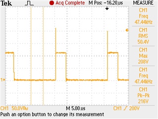
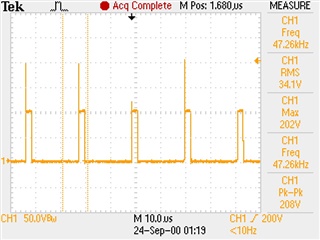
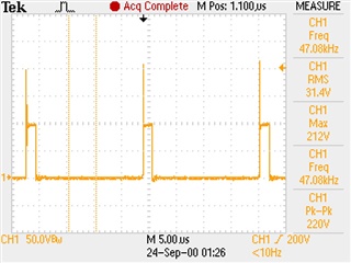
  • below are waveforms at across secondary rectifier diode which we are trying to replace with MOSFET 

    1) Secondary side , voltage across secondary side rectifier, Load current at startup = no load 

    2) Secondary rectifier , load current at startup = 2.4A 

    3) Secondary rectifier , load current at startup = 4A 

  • Hi ulrich,

    have you got these waveforms in below post 

  • Hi Hkul,

    Yes, I see the waveforms now, thank you very much. 
    As you probably have seen, the peak reverse voltage on the diode is shown as high as 212V when under a 4-A load at start-up.
    I believe the peak voltage can actually be higher than 212V for 2 reasons:
        1. You have the bandwidth limit enabled, so some of the peak may be filtered out, and
        2.  Image 2 shows that the oscilloscope sampling rate is too low to always capture the full peaks. 
    I recommend to remove the BW limit and to increase the sample rate to 4~8ns/point, if possible.

    That said, it is evident that the 200-V MOSFET is in danger of periodic overvoltage stress, and the 200-V diode is more tolerant of some overvoltage than the MOSFET is, or it would fail, too.

    Generally, this peak voltage at the turn-on of the primary-side switch is due to ringing of the secondary winding leakage inductance with the rectifier capacitance (diode or SR FET).  When the primary turns on, the rising voltage on the secondary charges up the capacitance of the rectifier. This charging builds up some current into the secondary leakage inductance which then rings with the rectifier capacitance.
    The SR FET may have higher non-linear Coss that the diode junction capacitance and the voltage may ring higher than 2X the reflected winding voltage.  

    As I see it, your alternatives are:
       1.  Choose a MOSFET with higher voltage rating,
       2.  Add a TVS clamp across the MOSFET to clamp the peak voltages lower than 200V, or
       3.  Add an R-C snubber across the MOSFET to absorb some of the energy to limit the peak voltage < 200V. 
    There are tradeoffs with each alternative.
    A higher rated MOSFET has no additional parts but may have higher Rds(on) or cost more.
    A TVS clamp is an extra part, with cost, but dissipates only the spike energy above its clamping voltage. 
    An R-C snubber is less expensive than a TVS, but dissipates power all the time, resulting in lower efficiency.

    I suggest to investigate each option and decide which is the best solution for your application.

    Regards,
    Ulrich

  • ok soon i attemp these alternatives,

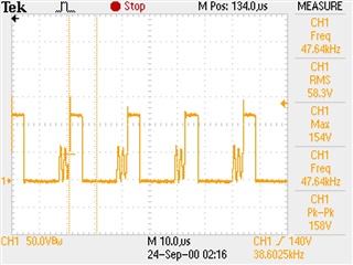
    below waveform is after startup, the regular running waveform at 4a load

  • Hello Hkul,

    Okay, good luck with your investigations.
    Please remember what I recommended about the oscilloscope bandwidth and sample-rate settings, in order to make accurate waveform assessments.

    Regards,
    Ulrich