This thread has been locked.

If you have a related question, please click the "Ask a related question" button in the top right corner. The newly created question will be automatically linked to this question.

BQ27531-G1: golden image not working well on target board

Part Number: BQ27531-G1
Other Parts Discussed in Thread: BQSTUDIO

I created a golden image by executing a learning cycle on the bq27531 EVM evaluation board.  I went through several charge/discharge cycles and it seemed to be working well.  However, when I programmed the bq27531 on my target hardware, it does not work as well. 

When charging, it will report 100% charged long before it has completed charging.  When it reports 100%, it has only passed about 60% of the charge that occurs in a normal charging cycle.  For example, on one charge cycle I started with the gauge reporting 5%, after fully discharging and relaxing for > 5 hours.  I charged until the gas gauge automatically stopped charging due to taper current being reached. Total passed charge for the charge cycle was 7115 mAh, which is consistent with what I was getting when using the evaluation board.  However, the gas gauge was reporting 100% after passed charge of 4229 mAh.  The gas gauge then just sits at 100%. 

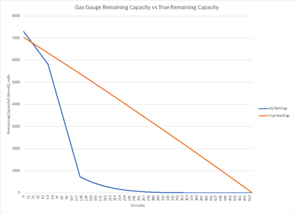
During the charge cycle, the full charge capacity adjusts up and down.  It first goes down, then goes up, usually ending up at a reasonable number.  In this example case it started at 4477 mAh, got as low as 3663 mAh, then ended at 7309 mAh.

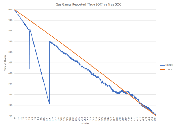
The discharge cycle is better behaved as the SOC reported tracks the true SOC reasonably well.  (I am defining "true SOC" by comparing passed charge with the total passed charge when I reach the terminate voltage).

I suspect this problem has something to do with executing the learning cycle by discharging the battery to its limit of 2.5 V, then changing Final Voltage and Terminate Voltage to my system minimum voltage of 3.5 V.  I also changed Design Capacity to 6000 mAh (about what I expected to get out of the battery under worst case current draw) and CC Threshold to 5400 (90% of Design Capacity).  When I made these adjustments on the evaluation board it worked great - the gauge started treating 3.5 V as 0% SOC. 

Comparing my data from the eval board and my system, one difference jumps out at me.  On the eval board, once I changed the voltages from 2.5 V to 3.5 V, Qmax never updated any more.  It had been doing small updates and seemed to be a reasonable value (13142 mAh vs. nominal battery pack capacity of 13400 mAh).   After programming the golden image onto my target hardware, Qmax changed to 7800 mAh after my first discharge / charge cycle.  It isn't clear to me if Qmax is supposed to be the total capacity of the battery pack or the capacity of the range Full Charge to Terminate Voltage.  Was I supposed to change Qmax when updating parameters for my Terminate Voltage of 3.5 V?

I have only gone through a few cycles so I'm not sure if the behavior will stabilize.  If so maybe I can create a new golden image?

Any thoughts on what the problem is here?  When updating post-learning cycle to match my system parameters, I changed Terminate Voltage, Final Voltage, Design Capacity, and CC Threshold to match my system low voltage limit and the observed available capacity (this is what SLUA903 says to do in section 2.1).  I don't think there is any drastic difference between the eval board environment and my target environment. The load currents are about the same.  As far as I can tell, loading a golden image did not entirely duplicate the state to the new gas gauge.  I suppose I could test this by programming the eval board with the golden image.

Thanks,

Dave

  • After running another cycle, behavior seems to be getting worse.  Plot below shows "True SOC" as reported by the gas gauge vs computed "True SOC" .  I am computing true SOC as 100% - Qpass / QpassFinal.  QpassFinal is 7041 mAh, the total passed charge across the discharge.  Current is not constant but doesn't vary much across the discharge.  Current starts at -769 mA and ends at -887 mA.  Discharge is from fully charged to my system minimum voltage of 3.5 V

    Remaining Capacity also behaves poorly.  Full charge capacity was reported as the same value, 7309 mAh, through the entire discharge.  However, the next morning when I applied external power to charge the battery, FCC was reported as ~1600 mAh, which then increases as it charges.  Unfortunately I don't have visibility into when it jumps down.  While discharging our system is polling on the I2C bus so I can't have bqStudio monitoring it.  Once voltage reaches 3500 mV my system shuts off and my log stops.

    Here is plot of RemainingCapacityFiltered() reported by gas gauge, vs true Remaining Capacity  computed as (QpassFinal - Qpass)

      For reference, here are plots of current and voltage as reported by gas gauge.  These look reasonable:

  • >I suspect this problem has something to do with executing the learning cycle by discharging the battery to its limit of 2.5 V, then changing Final Voltage and Terminate Voltage to my system minimum voltage of 3.5 V.

    Changing from a lower to a higher voltage is usually not an issue. The objective of the learning cycle is for the gauge to learn QMax and Ra. And that requires that you cover the whole depth of discharge range of the battery (a good approximation is a full charge to the max. charging voltage with a low taper current and 3000mV with a C/5 current).

    If you then change the terminate voltage from 3000mV to 3300mV, it will be compatible, because all you do is effectively prevent the cell from discharging all the way to DOD = 1.0. So that's not a problem at all.

    2500mV seems extremely low for a lot of chemistries. Unless you know that the ChemID goes all the way down to 2.5V, I wouldn't do this.

    Likewise, 3500mV is high for Terminate Voltage (because that will be above the voltage knee of many chemistries). This can lead to inaccurate capacity simulations, depending on chemistry.

    >I also changed Design Capacity to 6000 mAh (about what I expected to get out of the battery under worst case current draw) 

    This is a common mistake. Do not change Design Capacity. The gauge uses this for C rate based calculations and this should be set to the nominal capacity as per the cell's manufacturer. It must not be adjusted to what you want to get out of the cell. It's intended to be the nominal capacity and constant.

    The gauge will calculate FCC (full charge capacity) based on your charge termination and terminate voltage and load prediction settings so there is no need to manually adjust this capacity. At best, you will confuse the algorithm for any calculations it performs relative to Design Capacity and at worst you'll work counter to the adaptive nature of the algorithm.

    > Qmax changed to 7800 mAh after my first discharge / charge cycle.

    This must not happen. QMax = passed charge / change in DOD. Passed charge = coulomb count. If your sense resistor is correct (and CC Gain is correct) and if the ChemID is correct, then QMax won't just change to 50% of the learning cycle. So there is something seriously wrong. Either you didn't program the ChemID or you have an incorrect sense resistor or something went wrong during relax when the gauge updates DOD for QMax calculations.

    > It isn't clear to me if Qmax is supposed to be the total capacity of the battery pack or the capacity of the range Full Charge to Terminate Voltage.  Was I supposed to change Qmax when updating parameters for my Terminate Voltage of 3.5 V?

    QMax is a core measurement for the gauging algorithm. You must not update it manually. It must be measured by the gauge. It does this through coulomb count (passed charge) and OCV measurements (during relax) automatically. It's totally unrelated to Terminate Voltage.

    I suggest checking the accuracy of the current measurement (sense resistor, CC gain) and if you programmed the correct ChemID. The first problem you have to fix is the weird QMax update.

  • Dominik,

    Thanks for the reply. Sorry to be slow to get back to you.  I was out of the office Monday and Friday.

    Please see my responses below.  I have changed Design capacity back to the nominal battery pack capacity, and am going to do some testing on the dev board to eliminate any effect my target hardware has on this issue.  Once I have confirmed the golden image works on the TI dev board, I will move back to my target hardware.

    >> I suspect this problem has something to do with executing the learning cycle by discharging the battery to its limit of 2.5 V, then changing Final Voltage and Terminate Voltage to my system minimum voltage of 3.5 V.

    > Changing from a lower to a higher voltage is usually not an issue. The objective of the learning cycle is for the gauge to learn QMax and Ra. And that requires that you cover the whole depth of discharge range of the battery (a good approximation is a full charge to the max. charging voltage with a low taper current and 3000mV with a C/5 current).

    During the learning I discharged to a voltage of  2500 mV with a C/5 current.  I have four cells in parallel, each with a typical capacity of 3350 mAh (link below to PDF file where I got these specs from).  For design capacity I am using 13400 mAh which is what the battery pack is labeled as.

    Battery pack: https://www.batteryspace.com/custom-li-ion-18650-battery-3-6v-13-4ah-48-24wh-3-5a-rate-2x2e-e-ncr18650b.aspx

    Component cells: https://www.batteryspace.com/prod-specs/NCR18650B.pdf 

    > If you then change the terminate voltage from 3000mV to 3300mV, it will be compatible, because all you do is effectively prevent the cell from discharging all the way to DOD = 1.0. So that's not a problem at all.

    When I changed terminate voltage from 2500 mV to 3500 mV, I did not have any problems.  I went through 7 discharge cycles after changing terminate voltage and all values reported by the gas gauge seemed reasonable.  However I did notice one odd thing - Qmax never changed after I changed the terminate voltage.  Prior to that, it was updating after charging and discharging, staying close to the design capacity.  The final Qmax  update was to 13142 mAh.  It stayed at that number through all 7 discharge / charge cycles where terminate voltage was 3500 mV.

    >  2500mV seems extremely low for a lot of chemistries. Unless you know that the ChemID goes all the way down to 2.5V, I wouldn't do this.

    The component cell spec sheet linked to above states "Minimum Voltage, 2.5 V".  So I discharged the batteries down to that level during the training cycle, as my understanding for the instructions for the learning cycle were to discharge to the battery minimum voltage.  The ChemID was obtained using GPC tool.  From the report I got back:

      Best chemical ID : 2086 Best chemical ID max. deviation, % : 2.04

    This ChemID is for Panasonic NCR18650A.  Our component cells are Panasonic NCR18650B.  I don't know what the difference is, but I figured I should go with the ChemID produced by GPC.  Someone worked on this before me and ran into similar problems that I am seeing.  He used the ChemID for the component cells, but as our battery pack has some protection circuitry in addition to the cells, I was hoping the ChemID being non-representative of the battery pack as a whole was part of our problem.  

    Likewise, 3500mV is high for Terminate Voltage (because that will be above the voltage knee of many chemistries). This can lead to inaccurate capacity simulations, depending on chemistry.

    I am not familiar with the hardware design so can't speak to why the voltage is set at this level, but I did confirm this is the correct limit.

    >I also changed Design Capacity to 6000 mAh (about what I expected to get out of the battery under worst case current draw) 

    This is a common mistake. Do not change Design Capacity. The gauge uses this for C rate based calculations and this should be set to the nominal capacity as per the cell's manufacturer. It must not be adjusted to what you want to get out of the cell. It's intended to be the nominal capacity and constant.

    The gauge will calculate FCC (full charge capacity) based on your charge termination and terminate voltage and load prediction settings so there is no need to manually adjust this capacity. At best, you will confuse the algorithm for any calculations it performs relative to Design Capacity and at worst you'll work counter to the adaptive nature of the algorithm.

    I changed this per the instructions in slua903 Achieving the Successful Learning Cycle.  In section 2.1 it states: "After the learning cycle completes, [Design Capacity] can be adjusted to the actual amount of capacity extracted under the application's real conditions".  For my applications, with worst case current draw, this is about 6000 mAh.  In my testing I got about 7100 mAh, running at the low end of our predicted current draw.

    I did have to adjust the Charge Currents to account for the change in Design Capacity, to get the charging current I wanted.  For my future testing I am running with your recommendation of setting this based on the nominal capacity of the battery pack, which is 13400 mAh.  I set CC Threshold to 90% of this, 12060 mAh.

    >> Qmax changed to 7800 mAh after my first discharge / charge cycle.

    > This must not happen. QMax = passed charge / change in DOD. Passed charge = coulomb count. If your sense resistor is correct (and CC Gain is correct) and if the ChemID is correct, then QMax won't just change to 50% of the learning cycle. So there is something seriously wrong. Either you didn't program the ChemID or you have an incorrect sense resistor or something went wrong during relax when the gauge updates DOD for QMax calculations.

    Agreed this does not make sense and this big jump in Qmax happened at the same time the SOH and SOC readings started going bad.  

    >> It isn't clear to me if Qmax is supposed to be the total capacity of the battery pack or the capacity of the range Full Charge to Terminate Voltage.  Was I supposed to change Qmax when updating parameters for my Terminate Voltage of 3.5 V?

    QMax is a core measurement for the gauging algorithm. You must not update it manually. It must be measured by the gauge. It does this through coulomb count (passed charge) and OCV measurements (during relax) automatically. It's totally unrelated to Terminate Voltage.

    Your explanation of the Qmax computation makes perfect sense, but there is one detail I would like to understand.  You say it is unrelated to Terminate Voltage, but SOC as reported by the Gauge is related to terminate voltage, because terminate voltage is by definition 0% SOC.  I assume then in the equation for Qmax, the Gauge is using a separate computation of SOC that is relative to the full voltage range of the battery.  

    To use some concrete numbers from my data, on my first discharge after the learning cycle, I discharged from a reported 99% SOC to 0% SOC, with total passed charge of 12796 mAh.  Qmax would then be computed as 12925.  Qmax was updated 3 hrs 43 minutes after the end of the discharge, from 13186 to 13152.  So Qmax moved in the direction of the new computed value.

    I then charged it from reported SOC of 1% to 100%, with total passed charged of 12784.  33 minutes after the charge is complete, Qmax updates from 13152 to 13142.  So Qmax is updating in a way that makes sense.

    I then change Terminate voltage and Final Voltage from 2500 mV to 3500 mV.  I discharge from 97% to 0%, with a passed charge of 5400 mAh.  Two hours later, Qpass resets to 0, but Qmax does not change (this is the point at which Qmax usually is updated).  From this point forward Qmax never changes from 13142.

    If the gauge were to compute Qmax based solely on reported SOC, the new Qmax would be computed as 5400 / 0.97 = 5567 mAh.  Now I know from discharging to 2500 mV that the battery is only really discharged down to about 58% SOC, when you consider the capacity of the entire cell.  So change in SOC is only 42%.  Presumably the gauge knows this two if terminate voltage and final voltage do not affect Qmax.  The gauge would compute new Qmax = 5400 / 0.42 = 12857.  This is consistent with the prior Qmax computations, and I would expect to see Qmax update accordingly.  But Qmax never changes.  

    Qmax only changed when I load the golden image onto my target hardware.  It then changes to a value consistent with the total passed charged, but as if the computation did not take into account that 0% SOC as defined by final voltage / terminate voltage is really 58% SOC when you consider the total chemical capacity of the cells. 

    I suggest checking the accuracy of the current measurement (sense resistor, CC gain) and if you programmed the correct ChemID. The first problem you have to fix is the weird QMax update.

    I used the Chemistry tab in bqStudio to program the ChemID based on what GPC gave me.  It was working reasonably until I created a golden image and tried to run on my target hardware. I am now back on the dev board, which has never had the golden image loaded to it .  My next step is to load the golden image to the dev board to confirm the golden image works independent of running on my target hardware.

    I believe the current measurement is correct but have not been able to verify first hand.  I will make a direct measurement to confirm. 

    Thanks,

    Dave

  • Dominik,

    I wanted to post my latest results for anyone else who comes across this thread.  In summary - the root cause of my issue was setting Design Capacity to 6000 mAh (how much charge I could get under real system conditions) instead of 13,400 mAh (the battery capacity per the data sheet).  After programming the golden image to my target hardware, the first Qmax update was set to 7800, which is 130% of 6000.  The 130% is from the dataflash parameter "Max % Default Qmax".

    After creating a new golden image with Design Capacity set to match the battery data sheet (13,400 mAh) and set CC threshold to the recommended value of 90% of Design Capacity, the gauge is working much better.  

    I think this information in slua903 is incorrect.  This is from section 2.1:

    Design Capacity mAh is also used for state of health (SOH) calculations, and should first be set to the value
    stated in the cell datasheet. After the learning cycle (discussed in Section 3) completes, this value can be
    adjusted to the actual amount of capacity extracted under the application's real conditions. For example, if
    a cell datasheet specifies a nominal capacity based on charging to 4.2 V and discharging with 500 mA,
    but the target application actually only charges to 4.1 V and discharges with a 1000 mA load. In this case,
    the Design Capacity should be adjusted to a value determined through testing using the application
    charge and discharge conditions.

    I suppose you could argue my case is non-typical, in that we are only using about 50% of the chemical capacity of the batteries.  So for the typical design, this may not be an issue, as long as the true Qmax value is under 130% of the value used for Design Capacity.  

    One quirk of my setup now is that I get a low SOH, because SOH is computed as FCC / Design Capacity.  My FCC is about 7000 mAh, so the gauge is reporting SOH around 50%.  This is not really a problem since this number will not be visible to the end user.

    Thanks for the help,

    Dave