This thread has been locked.

If you have a related question, please click the "Ask a related question" button in the top right corner. The newly created question will be automatically linked to this question.

BQ27Z561-R2: External Temperature Sensor Accuracy

Part Number: BQ27Z561-R2

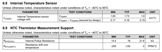
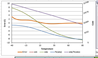
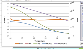
What accuracy (in +/- deg C) can be expected using an external 10k NTC thermistor (e.g. 103AT-2). If needed, for simplicity, the accuracy of the NTC itself can be ignored. If not, the application in question uses an R25 = 10k +/- 1% and B25/85 = 3435 +/- 1% part. Specifically, I'm interested in the accuracy at -30 C. Alternately, what is the size and tolerance of the internal pull-down resistor (which is in parallel to the NTC)? Thanks in advance!

  • Nic,

    Here is the information, from our datasheet which describes our error over temperature. 

    Thanks,

    Eric Vos

  • Thanks, Eric. I had already poured over the datasheet – especially prior to taking the time to ask this question (and link the related one).

    I believe the TS input is mux'd into the 16-bit ADC (effective resolution of 14-15 bits). I think it runs off the 1.8 V LDO, which can have a range of 1.6-2.0 V. However, I doubt that full range is used in the ADC. Obviously, the NTC and pullup resistor create a voltage divider, but even then I don't know the equation for conversion into degrees from that.

    The file here (from another TI E2E thread) indicates that the calculation is not that straightforward (hence the use of the solver) and that it is not linear across the operating temperature range. I'd be happy to use it, but I would need to know what kind of internal pulldown resistor is in parallel to the NTC as that is not indicated (or its existence for that matter) in the datasheet.

    I also have no idea what the 'resistance drift over temperature' spec means. Is it on top of the pullup resistor min/max?

  • NIc,

    You are correct in that the equation is not straight forward. It is actually a 5th order polynomial. The file you already attached is the file you would use to calculate the expected error. Using the default values for the other parameters is the correct thing to do. You should only need to replace the columns A/B with the thermistor you want to use. The error you are looking for should be included in the plot after you click solve. 

    I often refer to this link to back solve the PPM/degC math

    https://riedon.com/technical/understanding-temperature 

    Thanks,

    Eric Vos

  • Eric,

    Okay, thanks for the confirmation. I think I still need some more information to correctly fill out the form.

    • I'm assuming I should be using the 'host-side' analysis since the circuit in the datasheet looks most similar to that.
    • Cell B2 is 477.37... kOhm. Is that right as that is internal to the part? Is that where the 'resistance drift over temperature' spec comes in?
    • Just noting, the default values violate the recommended constraint in cell C7.
    • For this part, I believe merged cell F2/G2 should be zero since, per the TRM, all values (-32768 to 32767) are available.
    • Cells B17:C20 Need to be updated to include all the data in columns a and B. The default to only rows 29:38.
    • Similarly cells B21:C:23 need to be adjusted. I did coldest as rows 29:37, middle as 38:45, and hottest as 46:54.

    Finally, it looks like I would need to run this at least 4 times to cover all the scenarios. And, this assumes the ADC reference voltage ("Aadref", cell B11) doesn't move at all. It also doesn't include the whatever the resistance drift over temperature spec is.

    Vref (V) R1 (PU) (kOhm)
    1.6 14.4
    1.6 21.6
    2.0 14.4
    2.0 21.6

    Thanks.

    Nic Bergmann

  • Nic,

    I am slightly confused on the ask in terms of how it refers to the gauge. Our temperature reading (while somewhat close) is not a super accurate reading. It is very hard to gauge the error from part to part because the dominant error source is from the NTC itself, layout, and placement. 

    If your concern is gauging, at -30C you will have substantially different issues then just the NCT reading. If you are looking for a high precision temperature reading I suggest looking into another device. 

    The tools main purpose is to calculate new coefficients when using a different not recommended thermistor. I have added this thread to my team member who created a different calculator who should be able to help here. He returns from PTO tomorrow.

    Thanks,

    Eric Vos

  • Eric,

    I understand that the NTC itself has tolerances and therefore error. But the spreadsheet you referenced does not calculate the error of the NTC part, it calculates the error in the conversion to degrees within the TI part. If the ADC reference voltage can vary from 1.6-2.0 V and the pull up resistor on the TS pin can vary from 14.4-21.6 kOhm, it seems unlikely to me that the NTC will be the main contributor for error.

    I also don't need precise temperature readings at -30 or any other temperature. However, I would like to know what type of error to expect at various temperatures (including -30) as we have the gauge programmed to trigger interrupts according to temperature. For instance, if the interrupt triggers 5 degrees from the set value, is that a product of the gauge's accuracy or should I be investigating elsewhere.

    I think if you could just confirm the existence and size of the pulldown resistor within the gauge that is parallel to the NTC so that I can confidently fill out the spreadsheet, I should be able to handle everything else.

    Thanks.

    Nic Bergmann

  • Nic,

    It’s an 18k Ohm pull-up resistor to 1.8V.

    Hope this helps

    Thanks,

    Eric Vos

  • After manipulating the spreadsheet some, I think this is the default (i.e. uncalibrated) error.

    If the gauge's calibration routine is run, I think the error can be reduced to the following.

    These are both nominal and don't account for error introduced by the NTC itself or these other variables within the gauge.

    • Reference voltage – both for the pull-up resistor and ADC (nominal is 1.8 V)
    • 15-bit resolution – minimum is 14 bits
    • Pull-up resistor tolerance – nominal is 18k
    • Pull-down resistor value – nothing is listed in the datasheet, but the spreadsheet had a very specific default value (that was left as-is)
    • Whatever the 'resistance drift over temperature' specification is