This thread has been locked.

If you have a related question, please click the "Ask a related question" button in the top right corner. The newly created question will be automatically linked to this question.

LM25141-Q1: Controller switches ON/OFF when EN-Pin is between 0,8V & 2V

Part Number: LM25141-Q1
Other Parts Discussed in Thread: LM25141

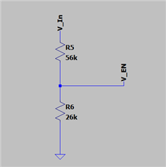
I have a voltage devider on the EN-Pin of the LM25141 device, which changes the internal hysteresis of the deivce from 0,8V and 2V to 2,5V and 6,33V:

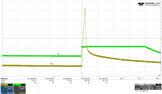
However, when I supply a voltage between these two voltage levels (independent if it is a falling or rising flank), the SMPS is currently switching ON and OFF:

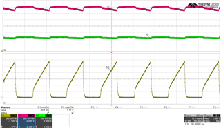
(red is Vin, Green is EN, Yellow is 3V3 output)

How can I create stable output voltages for rising and falling Vins in this voltage area?

  • Hi Florian,

    The EN function is not exactly a precision enable function. However, here are the applicable thresholds that may be useful for your calculations:

    Instead of 2V max, EN rising threshold is 1.45V min, 1.61V max (avg 1.53V)

    Instead of 0.8V min, EN falling threshold is 1.04V min, 1.2V max (avg 1.12V)

    There is a relatively wide hysteresis here that should accommodate input voltage ripple, etc.

    Regards,

    Tim

  • Hi Tim,

    one more problem here on our side...:

    We enable the 3V3 regulator, by a MOSFET in the supply path of the Voltage regulator. When we now switch this MOSFET on (@ 3,8V), the EN is rising and reaching 1,24V(green curve).

    This somehow makes the Regulator switch on for a short time what you can see in the yellow curve.
    If we keep this state, the regulator will remain OFF, until it reaches the EN-treshold.

    This is an unwanted behavour for us, as we want the regulator to stay inactive until ~4,2V.

  • Hi Florian,

    I'm not sure of your exact circuit configuration, but try holding EN low when turning on the supply FET. Also, check the input voltage waveform at turn on for overshoot etc. One possibility here is the input filter is undamped - connect an input electrolytic cap to resolve that.

    Please send the schematic if you need further assistance.

    Regards,

    Tim