This thread has been locked.

If you have a related question, please click the "Ask a related question" button in the top right corner. The newly created question will be automatically linked to this question.

TPS65150: TPS65150

Part Number: TPS65150
Other Parts Discussed in Thread: TPS65131

Hi,

We are using TPS65150 in our board. Attached the schematics of our design.

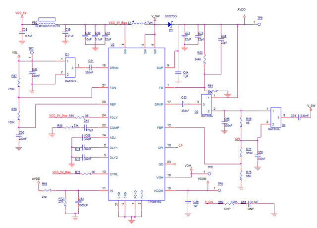
The set values are below.

Input : 5V
AVDD: 8.2V
VGH : 22V
VGL :-7

Currently we are facing issue with output voltage.
We are getting 5.4V at AVDD  instead of 8.2V and VGH and VGL voltages are coming near to 0V.

As per the datasheet, the Switching frequency is 1.2MHz, but when we probed the SW pin, the frequency is 14.6 MHz.

Please help us to understand the cause of this issue and us to solve this issue.

Regards,
Shafeeq

  • Hello Shafeeq:

    Schematics shows Fdly pin connected to 5v and I wanted to ensure that indeed is the case on the actual assembled board.  If it is, then boost should come up irrespective of charge pumps.  For boost diode I noticed that peak forward current rating is only 300mA and I wonder if that diode could be causing some issues during startup when boost output capacitors are charging at much higher peak current than 300mA

    Kind Regards,

    Liaqat

  • Dear Liaqath,

    Thanks for the reply.

    The diode we have used is SS22T3G and it supports average rectified current is 2A and peak current is 3A.

    Attached the snap of the datasheet of the diode.

    Please let me know if my understanding is wrong.

    Is there any other solution that you can suggest?

    Thanks & Regards,
    Shafeeq

  • Dear Liaqath,

    ++ below observation

    • In assembled board the value of R53 ( high side feedback resistor of boost converter) shows near to 100K ohm (if we remove the resistor and measure its value, it will show 344K Ohms.

    • Also when we turn on the regulator, the regulator output will go to 8.4V (set value by feedback resistors) and suddenly comes back to 5.4V and stays at 5.4V

    Regards,
    Shafeeq

  • Hello Shafeeq,

    The diode you provided the specification for should be good to use. Did you also check to see if the FDLY pin is connected directly to 5V on the assembled boards via the 0 ohm resistor? I would like to confirm that because of if FDLY is connected to 5V via 0 ohm resistor, boost converter should stay at 8.4V even if the charge pumps have an issue. If FDLY is in fact connected to 5V via a 0 ohm resistor, I do not see anything in the schematics that should prevent boost from ramping up to set voltage and staying there. In that case, I can only suspect some other board assembly issue like the center GND pad of TPS65131 not soldered properly or some other assembly issue.

    Kind Regards,

    Liaqat

  • Dear Liaqat,

    Thanks for the reply.

    FDLY is connected to VIN by 0 ohm in assembled boards.

    We have tested in different boards .
    We are not sure whether its because of assembly issue, as all boards shows the same behavior.

    And when we probed the SW pin of the regulator, the regulator switches at 300-600 KHz frequency, not at 1.2MHz

    Will there be any other possible cause for this issue?

    Also wanted to know, if we mount the required components for boost converter only (input and output Caps, Inductor, Schottky diode, feedback circuit, compensation circuit and FDLY 0E), will the boost converter will work irrespective of charge pumps?

    Thanks & Regards,
    Shafeeq

  • Hi Shafeeq:

    My apologies about the delay as I was on leave for few days. Did you get the boards to work?

    If the boost is switching at 300-600KHz, there likely is some assembly issues as i can not think of any other reason why it should not switch at 1.2-1.4MHz. Boost should come up irrespective of the change pumps.

    Kind Regards,

    Liaqat

  • Hi Liaqat,

    We have assembled a second batch of PCB from different EMS vendor. The current batch works fine without any issue.

    Thanks for all your support.

    Thanks & Regards,
    Shafeeq

  • Hi Shafeeq,

    Great to know that your issue is resolved and turned out to be some board assembly issue.

    Kind Regards,

    Liaqat