This thread has been locked.

If you have a related question, please click the "Ask a related question" button in the top right corner. The newly created question will be automatically linked to this question.

BQ76930EVM: Hardware configuration

Part Number: BQ76930EVM
Other Parts Discussed in Thread: BQ76930, BQ78350-R1

Please provide detailed information how to modify the BQ76930EVM hardware for 7S-1P battery. ( the user manual is not clear enough for me )

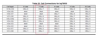
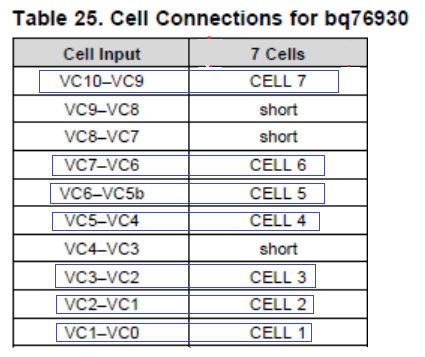
Which VCx should I short together etc.

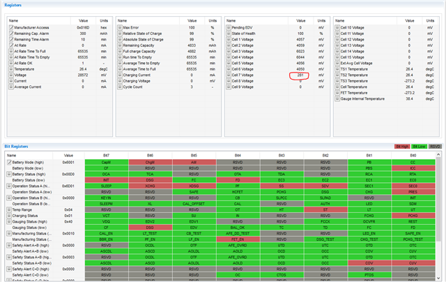
I followed the user manual and got strange cells voltage on some of the cells. 

please provide gg.csv file as well

Thanks

  • Hi Nati,

    See the BQ76930 data sheet table 7 for what pins to short together.  

    For a simple test with the EVM short Cell3 input to Cell 4, and Cells 7, 8, 9 inputs at the terminal block.

    If you are modifying the EVM board select the appropriate components from table 3:

  • As I wrote the tables are not clear enough for me.

    I understand the following:
    short  VC7 to VC8 to VC9
    short VC3 to VC4
    Remove: R23,R33,R24,R38

    I am not sure if I need to:
    remove R28,R38 

    I didn't understand what to do the blue marking: 

  • Hi Nati,

    Since you are using 7 cells on a part and board capable of 10 cells, 3 will not be used.  Those 3 unused cells are recommended to be cells 9, 8 and 4 of the BQ76930 as shown in the table.  When shorting the IC inputs the part will not have a cell voltage applied to those inputs.  The external balance transistors will need a path for current on the EVM, so the cell inputs need to be shorted at the terminal block of the EVM.  With the pins shorted at the IC and the terminal block, the EVM will have multiple parallel paths which will reduce the effective resistance from the terminal block to the IC pins.  Removing the resistors (R28, R38) removes those parallel paths so that the resistance is appropriate for the circuit.

    The blue marking in table 25 shows a mapping of the physical cells of the pack to the inputs of the IC.  Again the battery will have 7 cells while the IC is capable of 10.  Counting cells from the bottom up:

    • The BQ76930 IC cell 10 inputs are used for Cell 7 of the battery
    • The IC cell 7 inputs are used for Cell 6 of the battery 
    • The IC cell 6 inputs are used for Cell 5 of the battery 
    • The IC cell 5 inputs are used for Cell 4 of the battery
    • The cell 3 down to cell 1 inputs match.

    You asked about the gg.csv file in your first post which I missed.  In the BQ78350-R1 you will need to set the  AFE Cell Map to match the cells used, this is much like the map shown, set a bit to 1 to match the cells used.  For 7 cells shown in the table above set 0x0277.  See the BQ78350-R1 technical reference manual section 2.6.3 AFE Cell Map for details.

    Select other settings in the BQ78350-R1 as appropriate for your design.

  • This is the voltage that I have got after making the modification

    Cell7 = 281mV instead of 4050mV

  • Now its working fine. Thanks for the support