Hello All,
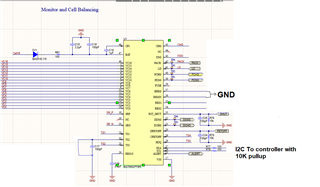
I have a custom board for BQ76952PFBR

sharing image of the schematic
I have already soldered 33E, 100nF filters on Sense voltage input pin VC16-VC0
also, I have an external voltage divider on all the VC pins to emulate the behaviors of the cells
I can measure 1.8V on REG18
REG1 and REG2 are not used hence REGIN and BREG are connected to GND
TS2 pin is also connected to GND to avoid the chip to shut down (No response on I2C when TS2 is floating and it measures 1.4V on floating )
I2C lines are connected to the controller with 10K pullups on 3V3
In the above conditions, The chip responds on I2C on stack voltage from 5.6V to 13V (Sometimes 18V)
After 13-18V the chip stops responding on the I2C lines however 1.8V is still present on REG18
Also, can it be something related to OTP programming
because the chip can be programmed in OTP mode when stack voltage is between 10 to 12V
Thanks in advance
Rushab

