This thread has been locked.

If you have a related question, please click the "Ask a related question" button in the top right corner. The newly created question will be automatically linked to this question.

TPS650864: Troubleshooting PMIC used to power Xilinx ZU3

Part Number: TPS650864
Other Parts Discussed in Thread: LM5143

PMIC_HIGH.pdf

Hi,

In one of our recent design we are using PMIC TPS65086401RSKT to power up the Xilinx FPGA ZU3. The Power architecture is we have a 24Vdc power as input to this board which is first fed to a buck (LM5143) to generate 12Vdc. This 12Vdc is the input to PMIC to generate different power rails required by ZU3. 

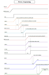
The power-up sequence is as in below snap shot. (The load switch used is TPS22959DNYR). attached is the draft schematics for this block alone. The voltage rails (VCC_5V_PMIC, VCC_12V are generated using LM5143)

The issues that i am facing are,

1) During the board bring up , since all the power rails of the FPGA are not up yet, because some of the rails are sequenced using GPOx's and which are not configured. Is there a way to configure this PMIC (GPOx's) without using I2C programming? Manual method. (As of now none of GPOx's are giving any output, so my sequence is not getting completed).

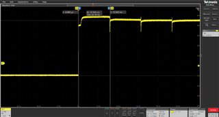
2) Since CTL1 is at 3V3 (with input VSYS=12V, LDO3V3 available), The Buck1 out is available, but the waveform looks something like this, and from one of the post in this forum I came to know that this pattern is due to Power Fault. So how can this power fault occur? ( I mean i checked for any shorts with GND but none) . The voltage reading from the scope was around 1V75 (ignore DVM readings from the snap).

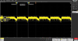
3) I am also able to see Buck2 op. The voltage reading is around 0V865 from the scope.

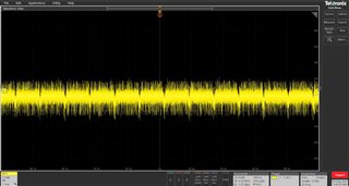
4) as per our sequence the Buck 6 should have been up (with CTL3 = LDO_3P3, CTL2 = GND). But its not showing any voltage. 

Can you support me in debugging these issues ? Let me know if you need any other details.

With regards,

Sandeep P

  • Hi Sandeep,

    Thank you for the questions. A power fault does seem likely from the scope shots. So it would be attempting to start and then trying to restart due to a power fault. In order to further investigate, please provide a scope shot of the startup of Buck1, Buck2, LS1, and Buck6. This may be able to identify when the power fault is occurring.

    Thanks,

    Daniel W

  • Hi Daniel,

    Please find attached the startup of Buck1, Buck2, LS1, and Buck6. I hope my understanding of startup is to capture the Vout of buck as soon as we power ON or provide input to the Buck is correct? Let me know if I am wrong. Since I had shared schematics in my previous message, I have added the Output caps designators name into snap shots file name for your reference. Also, the Buck 6 output is close to 0V. its not up. 

    Scope_shots_04AUG2021.zip

    I was also checking the power rails order and found that VSYS & LDO3P3 are good, but LDO5P0 is abnormal, please see below scope shot.

    1) Can you please also provide feedback on my previous reply point #1?

    2) What are the default settings if we don't do OTP or any other configuration to the PMIC and just power on.

    Thanks,

    Sandeep P 

  • Hi Sandeep,

    1) The GPOs are only OTP configured. For the TPS65086401RSKT they act as powergood outputs so in the event of a power fault, they will stay low.

    2) The default configurations for the TPS65086401 can be found in section 8.4 of the Datasheet.

    https://www.ti.com/lit/gpn/tps650864

    From the scope shots it seems likely that there may be a power fault on Buck 6. Please try to start the pmic with buck 6 disconnected from what it is supplying and instead use an external 1.2V output.

    Thanks,

    Daniel W

  • Hello Daniel,

    Thanks for giving a direction towards debug. Let me try this and update you. 

    Thank you