This thread has been locked.

If you have a related question, please click the "Ask a related question" button in the top right corner. The newly created question will be automatically linked to this question.

TPS25947: tps25947l has no voltage output

Part Number: TPS25947

Hello:

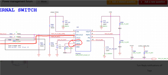
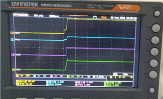
1.our project has encountered a problem: tps25947l has no voltage output.

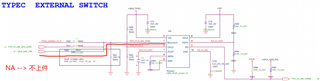
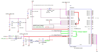
2. Application: + VBUS_ TYPC 100W(20V 5A)。 Practical application in type C adapter voltage conversion

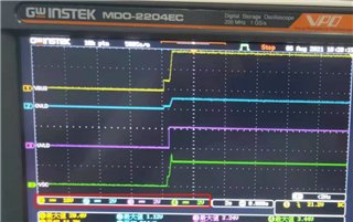
3. The circuit is as follows. The actual measured V+VBUS_TYPEC  and EN have voltage, but Vout (+ VDC) has no voltage output.

Please help us study whether the circuit design is OK and share with us any good suggestions,

Note: VBUS_ SINK_ CTRL is from PD IC (cypd6227).

  • Hi Jimmy,

    1. Is it LM73100 device or TPS25947? If TPS25947 then which variant, what is full device name?

    2. How much is input voltage and EN voltage?

    3. Is there is some load that is drawing current at output?

    4. Is this happening on first time starting the board or output was coming earlier and now it stopped coming?

    Regards

    Kunal Goel

  • Hi Kunal:

    1. Is it LM73100 device or TPS25947? If TPS25947 then which variant, what is full device name?

                       --》TPS259474LRPWR


    1. How much is input voltage and EN voltage?

              --> input 20V  and EN: 2.2V 


    1. Is there is some load that is drawing current at output?

                    --> 5A 

    1. Is this happening on first time starting the board or output was coming earlier and now it stopped coming?

            --> first time 

  • Hi Jimmy,

    What kind of load is it ? Is it always drawing current or it draws full 5A current after efuse is on and giving 20V at output?

    Regards

    Kunal Goel

  • Hi Kunal:

     It is type-c adapter ,  it will supply power for MB . 

          Our design the max power 100W (20V 5A)

  • Hi Jimmy,

    1. Pin 9 is ILIM pin . Is resistor value at this pin 499 ohm? Recommended value is above 549 ohm.

    2. Can you share a waveform like this that shows efuse input , output, EN voltage and current through device? :

    Regards

    Kunal Goel

  • Hello Kunal:

    1. Item1 --> 499ohm have changed to 620
    2. Item2  --> waveform as below  , the loading is amost '0' A.

                    Ch1 --VBUS (Input)

                    Ch2 --OVLO

                    Ch3 -- EN.UVLO

                    Ch4 -- VDC(Output)


      Thanks!

  • Hi Jimmy,

    1. One reason I can think is that from waveform OVLO voltage looks close to 1.2v which is the threshold for overvoltage turnoff. Can you check how much is exact voltage on that pin?

    2. Also how much is total output cap at eFuse output?

    3. Can you also probe current in above waveform?

    4. I see output does start to rise but then settles at around 2V. Does it finally goes to zero?

    Regards

    Kunal Goel

  • Hello Kunal:

    1. Our design circuit is shown in pdf file. The input and output capacitor can directly see the circuit part.

    2. For tps25947, In view of the current problem, can we make further analysis through other experimental methods.

    a. Input

    b. Output

    c. EN/UVLO

    d. OVLO

    e. PGTH

    f. Rimon

    All parameters can be modified and provided through experiments.

    3. Please help study the circuit and IC working principle and share some good suggestions to us. Thank you!

    TPS25947 Design Schematic.pdf

  • Hi Jimmy,

    I did not understand your point 2. Can you explain?

    I have seen schematic . It is fine. Just one comment:

    I see that GND signal is not there at IC GND pin? Can you check this? Is IC GND pin connected to GND signal in layout?

    Regards

    Kunal Goel

  • Hello Kunal:

    My client knows the grounding problem and have rework, but the result is the same as fail

    At present, we have two projects that will use this material, and the design is exactly the same.

  • Hi Jimmy,

    You shared this waveform and I asked you these question earlier . Please answer these question:

    1. One reason I can think is that from waveform OVLO pin voltage looks close to 1.2v which is the threshold for overvoltage turnoff. Can you check how much is exact voltage on that pin?

    3. Can you also probe current in above waveform?

    4. I see output does start to rise but then settles at around 2V. Does it finally goes to zero?

    5. Can you check with multimeter voltage on output pin?

  • Hello Kunal:

    1. One reason I can think is that from waveform OVLO pin voltage looks close to 1.2v which is the threshold for overvoltage turnoff. Can you check how much is exact voltage on that pin?

          --》 Vovlo=2.2V   please view waveform .

    1. Can you also probe current in above waveform?

               --》In advance ,  We can not measure by probe current.  but we can't cut off out loading . 

               --》 Result : still fail.

    1. I see output does start to rise but then settles at around 2V. Does it finally goes to zero?

               --> No Zero。

    1. Can you check with multimeter voltage on output pin?

               --> 2.4V 

  • Hi Jimmy,

    Voltage on OVLO pin is looking around 1.2V . I think that is disabling part. Can you check exact value of resistor R899 and R900 on board with multimeter?

    Also can we try with low voltage less than 20V say 15V at input and then see what is output?

    Regards

    Kunal Goel