A related question is a question created from another question. When the related question is created, it will be automatically linked to the original question.
If you have a related question, please click the "Ask a related question" button in the top right corner. The newly created question will be automatically linked to this question.
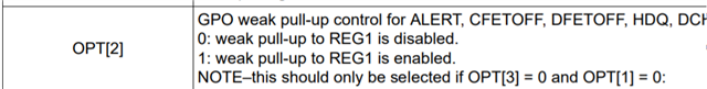
The BQ76952 has several multi-function pins named with their primary use but with various configuration bits which change based on the selected function. As an example see table 6-5 of the technical reference manual compared to table 6-6. The hierarchy of the bits is not explained other than the notes. For OPT[2] as shown above:
If OPT[1] = 1 the pin would be driven to a high state, so the pull up of OPT[2] would not be effective, apparent, or desired.
If OPT[3] = 1 the pin would be driven to REG1 if driven. It is not clear why this bit would have an effect if OPT[1] were 0, but it is easy enough to set.
So for the 3 bits OPT[3,2,1] the practical settings would seem to be:
0,0,0: No pull up, high impedance when "high", use with external pull up.