This thread has been locked.

If you have a related question, please click the "Ask a related question" button in the top right corner. The newly created question will be automatically linked to this question.

Li-ion battery charging using the 19V Adapter.

Other Parts Discussed in Thread: BQ25730, BQ25723

Hi, support team

My customer has the questions as follow:

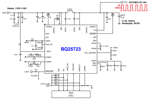
Please recommend an IC that satisfies the following conditions:

(1) 19V Adapter is used.(Adapter output tolerance +/-5%, 19.95Vmax)
(2) It would be better to use an internal FET(BATFET) for the charger.
(3) The BATFET must be continuous-current.(9A or more)
(4) I2C control method.
However, it should be possible to default-charge the battery when the adapter is inserted
(without I2C control)
(5) BATT's UVLO is controllable. because, a momentary voltage drop occurs in the low voltage battery.
(reason of the high-current, ~8A@60ms)
(6) SYS output is required. (continuous current ~5A). Excluding charging current.

Thanks so much.

Best regards,
Yuki

  • Hi Yuki,

    TI does not have an integrated FET that can meet item 3.  The closest fit is BQ25730 with external FETs but like all of our charger's, it does not have controllable BAT UVLO.

    Regards,
    Jeff

  • Thank you for your response.
    Not all features can be satisfied.

    (Assuming.. designed with BQ25730..)
    When a momentary voltage drop(high current 60ms, ~8A), can I refer to VSYS_UVLO(FALLING) for UVLO while using battery? (min2.2V / typ 2.4V / max 2.55V) What is the recognition falling timing?
    When inserting the adapter, "SYS" should be always output with battery voltage 4.2V.
    Is there a minimum and optimal schematic guide?

  • I drew the operating state of "SYS" on the charger
    Please check it.

  • Hi Q,

    Thanks for reaching out.

    1. The buck boost controllers, which include BQ25723 and BQ25730, cannot be used standalone. It needs I2C control at all time.
    2. The IC is powered by the battery and that voltage is determined by your battery. There should not be any momentarily drop in your battery voltage. Regarding VSYS voltage in no adaptor situation, you can think about this part as just a DC power supply (battery) with a switch (BATFET) always on. So no, VSYS should not drop so much because the switch is always on and your battery voltage will not change that much. The VSYS caps also holds up that voltage.


    3. VSYS will be regulated when an adaptor is available.

    The best way to start is to refer the the EVM.

    Thanks and I hope this helps,

    Peng

    *Please press "This Resolved My Issue" on the thread if my answer is satisfactory

  • Can I ask an additional question?


    (1) As attached image, is it possible to design only the Buck converter's FET circuit?


    (2) Other manufacturers IC(VSYS capacitors) could not compensate for the Battery voltage.
    (In case of instantaneous current consumption operation)
    Is VSYS capacitor(10uF) enough for this product(BQ25723)?

  • Hi Qiu,

    1. Unfortunately the answer is no, you need all 4 MOSFETS if you use BQ25723.

    2. 10 uF is just the label on the block diagram, we actually have more on the EVM. You will need more than 10uF. This answer to this question is complicated because it is dependent on your slew rate, load current transient amount, etc. In general, it should be fine if you reference the EVM. You can tune the circuit afterward if needed. 60 ms is not a very fast transient time. Transient only applies when the IC is regulating the voltage on the SYS rail. In battery only condition, battery will do the majority of the lifting to hold up the SYS rail.

    Thanks and I hope this helps,

    Peng

    *Please press "This Resolved My Issue" on the thread if my answer is satisfactory