This thread has been locked.

If you have a related question, please click the "Ask a related question" button in the top right corner. The newly created question will be automatically linked to this question.

TPS543820EVM: TPS543820

Part Number: TPS543820EVM
Other Parts Discussed in Thread: TPS543820

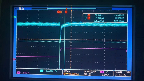
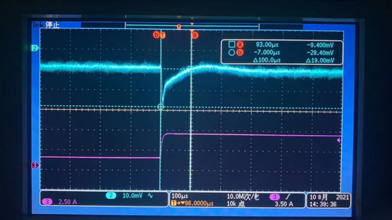
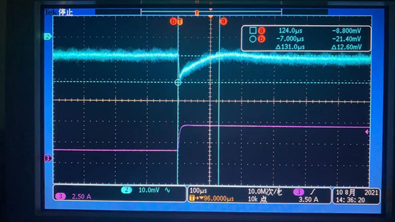
Q1:On the evaluation board U2 of tps543820, the output capacitance is 2 22uF and 1 47uF, the slope compensation is 4pf, and the load change is 0-5A. Why is there a step on the output waveform. Why does the output have overshoot but no oscillation?

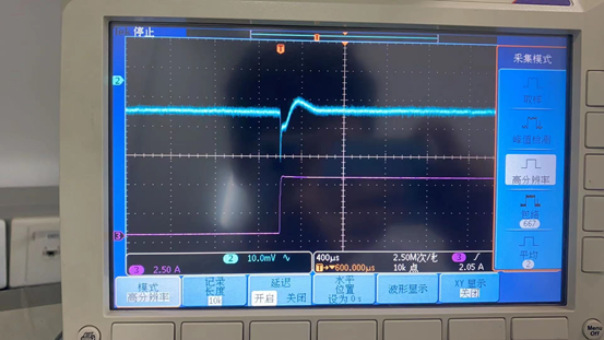
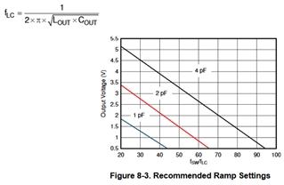
Q2:I conducted a Simplis simulation on tps543820. When analyzing the Bode diagram with slope capacitance of 1pf, 2pF and 4pf, their bandwidths are 58khz, 95khz and 135KHz respectively. In the tps543820 module board, experiments were carried out in three cases respectively. It was found that the dynamic response was the fastest in 1pf and the slowest in 4pf. As shown in the figure below, why did the larger the bandwidth, the slower the response?

  • Hi Chris,

    Two generic comments that I would like to make before answering your questions are:

    1) The compensation loop in TPS543820 is not a traditional one, and does not necessarily act like a standard external compensation loop.

    2)  You should not expect all slope capacitances to be able to properly compensate your plant.
         There is only one capacitance configuration that will probably offer you the expected performance. And one may even be unstable.

    Now to your first question. The output voltage is not mentioned, so I assumed Vout=1 V.
    If indeed you are regulating 1V and the output capacitance is 2 22uF and 1 47uF, the slope compensation should probably be selected as 1pf,

    This is because Fsw/Flc will result 46.5, which leads us to the 1pF area.

    In this case, configuration of compensation ramp as 4pF is probably unstable (for this LC).
    Also, you should not expect oscillation after an undershoot, first because this is not a typical loop configuration, secondly because it is not configured as recommended. Same applies to anything else that may not look proper with this waveform.

    Regarding your second question. Please note that in spite of longer settling time for higher capacitance configuration, the transient response/drop itself is better for higher ramp capacitances. Also, as previously mentioned not all ramp capacitance configurations are going to be acceptable for a single output stage.
    Cff will also play a role in achieving the expected transient response.

    Hope this helps.

    Regards,

    Yitzhak Bolurian

  • Hi Bolurian,

    This is Chris. Thanks for your strong support and I have learnt more from your response. However, I still have some concern and I look forward to your response.

    Why does the setting time turn longer when I set Ccamp larger, which means that the bandwidth is turning higher?

    On the other hand, the setting time should be connected with bandwidth. I think the setting time should be more shorter when bandwidth turns higher.  It is just my assumption and I hope you can give me some explanation on it.

    Thanks and if you have any question, pls feel free to let me know and I'll give you feedback as soon as possible.

  • Hi Chris,

    Even in traditional externally compensated loops, the settling time is not solely a function of Fco, but it also depends on phase margin and other factors. The structure of the internal compensation in TPS543820 is very different, so that assumption does not even apply here.

    Regards,

    Yitzhak

  • Hi Bolurian,

    Thanks for your response, which help me a lot.

    Thanks and Best Regards!

    Chris

  • Hi Chris,

    Thanks for confirmation.

    Thanks,

    Lishuang