


Hi,
I’m now evaluating BQ24315 OVP/OCP IC in my PCB board. So far, I’ve encountered a technical issue which I would like to share and seek advice (if any) as I still can’t figure out yet after round of experiments.
Please refer Figure 1 for simple block diagram (CH1 = power supply input (yellow), CH2 = VOUT from BQ24315 OVP/OCP IC (green), CH3 = /FAULT pin with pull up to 1.8V (red)) to illustrate circuit application.
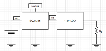
Figure 1 – Original circuit application
In Figure 2, it presents all waveforms that I’ve captured so far. I’ve introduced an input voltage step change from 6V (OVP trigger at about 5.85V = VOVP) to 5V (expect output voltage recover immediately as usual). As you may noticed, it’s obvious that output voltage (as well as /fault pin) suffers sort of undesired oscillation and take about 180ms to stabilize. It’s out of my expectation when I compare this behavior with respect to waveform presented inside BQ24315 IC datasheet.
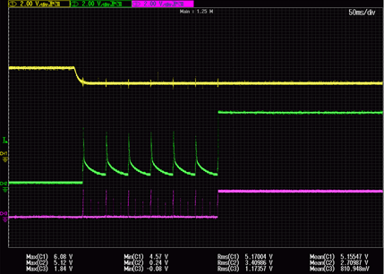
Figure 2 – Waveform captured with original circuit application
After some troubleshooting, I found out that above-mentioned abnormal behavior will be resolved when I added extra 1ohm in between BQ24315 IC GND and power supply GND (refer Figure 3 for modified block diagram and Figure 4 for waveforms captured).
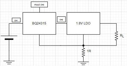
Figure 3 – Modified circuit application
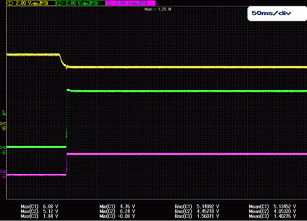
Figure 4 – Waveform captured with modified circuit application
However, I still can’t figure out why additional 1R will help to solve undesired oscillation during input step change from 6V to 5V and what to cause such undesired oscillation.
Please kindly share your view in this matter, thank.

