This thread has been locked.

If you have a related question, please click the "Ask a related question" button in the top right corner. The newly created question will be automatically linked to this question.

TPS7B81-Q1: PSRR data

Part Number: TPS7B81-Q1

Hi team,

How much does the output capacitance value affect the PSRR performance?

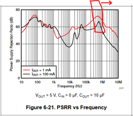
I would like to request a PSRR vs frequency plot for TPS7B8133-Q1 and TPS7A6633-Q1 just like Figure 6-22 in the datasheet of TPS7B8133-Q1.

My condition is Cin=1.0uF, Cout=2.2uF, Vout=3.3V, Iout = 10mA 

while Figure 6-22 is Cin=0uF, Cout=10uF, Iout = 1mA or 100mA

I would like to know how much Cin/Cout value affect the PSRR performance. 

regards,

  • Hi Shinji,

    The output capacitor mainly affects the PSRR at high frequencies, beyond the bandwidth of the LDO.  The graphs for the TPS7B81-Q1 were captured using an output capacitor of 10uF.  With 2.2uF on the output, the high PSRR peaking around 1MHz will shift to a slightly higher frequency, then roll off.

    The input capacitor effects are not captured in these plots.  PSRR is typically taken with no Cin, as the addition of an input capacitor makes it harder for the test equipment to drive a high frequency ripple into the LDO.  If you increase Cin you can usually expect the amplitude of the input ripple to decrease, but you would have to evaluate your system to determine how much it increases as this also depends on what the source impedance is that is driving Cin (and the LDO).

    Thanks,

    Stephen

  • Hi Stephen,

    How much is the BW of TPS7B81-Q1?

    regards,

  • Hi Shinji,

    The bandwidth of the LDO is not fixed and depends on load, tolerance, Vin, etc.  What I meant to say is that, Cout mainly impacts the higher frequencies.  At these values of Cout (1 uF to 10 uF or 22 uF) you typically will see a boost in PSRR from 500 kHz to 10MHz. 

    Thanks,

    Stephen