This thread has been locked.

If you have a related question, please click the "Ask a related question" button in the top right corner. The newly created question will be automatically linked to this question.

Trouble applying power converters

Other Parts Discussed in Thread: TLV1117, TPS7A92, TLV767, TPS745

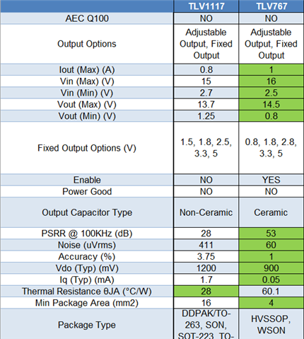
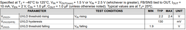
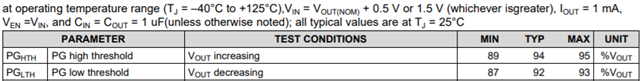
This question isn't necessarily about a TI part, but you do sell regulators that I'm interested in. My problem has to do with using these imported isolated 1 watt DC-DC power converters. I did a design that uses one single output and one dual output, the trouble is with the dual which is 5 volt input +/-12V output. I was feeding the input with a part like TLV1117 so overvoltage wasn't possible, but its input was fed with a wall wart whose output was "erratic" and the dual converters kept blowing up even without a load. So the only "problem" could have been operating with undervoltage. Now I have three different vendors for these parts, but in truth they could all be coming off the same production line in China, and the product support for these parts is nonexistent. I can look at any of these "data sheets: (really they're just product matrices) and there is zero indication that "undervoltage lockout" is needed. And interestingly the single didn't have a problem with any of this! Now I know you have some parts (TPS7A92 comes to mind, that one's probably overkill for the job) that are linear regulators with UVLO, but I just wanted to know if you think "burying" a design requirement for the supply by deliberately not publishing it is now "par for the course", or if anyone here has any experience with these little time bombs?

  • Hi Jeffrey,

    I can't comment much on what other companies may find to be acceptable but many companies make these 1117 type LDOs which are pretty old designs and so specs like UVLO weren't always common place when they were released. So they may not have been designed with a feature like UVLO or they may not have characterized it since it wasn't a common spec. This may explain why you're not finding all of the specs you are used to using to complete your design. 

    For more modern LDOs TI tries to provide datasheets which have all the information needed to complete a design and I agree TPS7A92 is probably overkill for an 1117 type application since you likely don't need the very low noise of TPS7A92. What about TLV767? We specifically designed this part as a modern device that can be used to improve on 1117 type devices. TLV767 does have UVLO  which typically releases at 2.2V. 

  • Well you see that's part of the issue, a fixed voltage lockout may not give me the protection I need.because I don't know what I have to protect against, since it's not on the Converter's data sheet!! So  it looks like I need to make certain the output doesn't go very far below 4.5 volts, maybe by s few tens of mill volts. Anyway what I really need is expertise with the converters because if they fail in the field at any rate at all I'm screwed. I assume you're familiar with these parts? They're available from just about every major distributor and from aliexpress. SOMEBODY with a technical capacith must now how to protect these parts, even though emails to aimed, gaptec and CUI so far have yielded nothing coherent.

  • Hey Jeffrey,

    I can't really say much about competitor devices, but generally when LDOs are damaged the two most common ways that it happens are reverse current and/or abs max violations. 

    1. Reverse Current: This happens when Vout is greater than Vin and the LDO does not specifically specify that it has reverse current protection (the majority of LDOs do not have reverse current protection). 
      1. Often occurs during shutdown or brown out events when the output is lightly loaded.
      2. For more info on Reverse Current see this link
    2. Other Abs Max Violation: There can be many different abs max conditions to look out for and it varies by device but often the input voltage is often the one most likely to be violated (either by going too high or far below ground).

    So I would recommend putting a scope on your input, output, and adjust pin (for a floating LDO) and then run your system through all of its startup, shutdown, load transients and any possible brown out events and monitor for either of these conditions. 

    If you don't feel like the devices you are using provide you this information then I would reach out to the manufacturers to get the information. It sounds like you tried with other companies and if they are unwilling to supply it then I would consider moving to more responsive/reliable manufacturers. If you have any questions which aren't covered in a TI datasheet you can always post a question here on E2E and we'll do our best to get you what you need. 

    Example Abs Max table for TLV767

  • It's not the LDO getting damaged, it's the power converter that I'm using the LDO to try and protect. What I'm saying is the isolated 1watt dual voltage power converter appears to be hypersensitive to input under voltage, to where that condition will burn out the converter even with no load. But this sensitivity isn't even mentioned in the data sheet. Do you have any LDOs that will shut down cleanly if tne input voltage drops just enough to prevent the output from putting out the minimum 4.5 volts? If not how am I going to be able to use thesr parts in a real design? Does TI make any isolated power converter modules? How can these vendors sell a product whose spec sheet isn't complete enough to be able to use it withoit burning up all the converters?

  • Ah, I thought the LDOs were being damaged. What about using an LDO with an enable signal and then use supervisor to monitor the input voltage and shutdown when Vin drops below a certain point?

  • Why should I have to go to a multi chip design to protect a $2.70 part? Why is it so finicky in the first p!ace? Why can't somebody give me the actual spec I need to meet to guarantee that I won't be destroying the part?

  • Hi Jeff,

    Some of our customers will purchase a Texas Instruments EVM of the power converters they wish to use and run a series of tests.  This is done to confirm the device matches their understanding of the datasheet.  If a test produces a result which falls outside of what they were expecting, they come back to this E2E forum and provide that data to us with their questions.  We have dedicated engineers to this forum so we try to be responsive to customer questions.

    Personally I find that our Texas Instruments datasheets are among the most comprehensive in the industry, especially our latest devices which include the latest graphs and curves, so you should find all of the details you need for your design.  Of course, over time the industry adds new graphs to datasheets that may not have been a concern to customers in the past.  So where a part was designed 30 years ago may not have many transient response curves, for instance, modern parts list those graphs in the datasheets.

    Since the switching modules are giving you trouble, I recommend reviewing the modules from Texas Instruments. You can submit your requirements to E2E and one of our engineers can assist with some options.  Then purchase an evaluation board of the power module(s), and test to confirm they work as you believe they should.  You can also purchase the evaluation modules of each power converter (LDO included), connect them together and confirm the system works as you anticipate.  And ask questions on E2E if something does not look correct, we are here to help.

    Thanks,

    Stephen

  • Well unfortunately I've "exhausted" one vendor for product support but I'm currently pursuing six others (this is getting frustrating quickly). But what seems to remain is I'll still have to "craft" some undervoltage protection, as soon as someone will tell me what I'm obligated to protect against! Yes as long as I'm here at a TI forum let's take at the TLV76750, it says "typical" UVLO+ is 2.2 volts and UVLO- is 1.9 volts I guess the difference between them is hysteresis. Now I haven't had to design with a chip with lockout before, is that referenced to the input, the output or is it the difference? In theory from what I know now I may need to disable the output when it drops below 4.499... volts (OK let's say 4.4) for more than say a couple of milliseconds. From the schematic it LOOKS as if the UVLO voltage is referenced to the input which isn't even close to what I would need. The situation is generally that the typical "problem" has something to do with some uC "going funny" at low input voltage, but the problem I'm having is purely analog, SOMETHING (I don't understand what yet) is pulling too much current when it tries to "execute the converter algorithm" at input undervoltage (which referenced to the LDO is of course its output), and the device permanently self-destructs with no warning and no possible recovery. Do you have a device for 5 volts and about 500-1200 ma range of output with a tight output-referenced lockout like that, or am I constrained to send disable for an LDO with an enable pin from an output supervisor chip?

  • Hey Jeffery,

    Yes the UVLO voltage is referring to the input voltage, so relying on it to turn off when the output voltage drops below ~4.4V won't work since UVLO won't turn off until Vin drops below ~2.07V (some devices/conditions may not turn off until Vin drops to 1.9V). 

    UVLO Spec for TLV767

    We don't have a lock out where the output would turn off if output drops too far. However could you use a PG (power good) pin to enable/disable the micro? Power good monitors the output voltage and provides a high signal when the output exceeds  ~95% and will shutdown when if falls too low. If shutting down the micro if Vout drops (instead of shutting down the LDO output), then you may want to consider TPS745 or TPS746 which are 500mA and 1A LDOs with PG. If those aren't exactly what you need, here is a filtered list of our LDOs which support 5V out and with a max output current between 500mA and 1.5A which have PG.  

    TPS745 PG spec

  • So I haven't posted in awhile. Here are my latest findings:

    The single-output converters don't appear to have any "special requirements" with regard to the source impedance of the supply or of their surge current at startup. The "garden variety" duals, however, are EXTREMELY demanding for input surge current, and if this (unpublished) requirement isn't met, these modules will fry almost immediately. This is apparently because these parts are being made and sold in a hypercompetitive commercial environment, forcing these modules to be manufactured with a specific design that is particularly intolerant of low available surge current. There is a solution, however, if one simply purchases only from vendors which say on their data sheet "3 year warranty" then there is no surge current requirement, since the vendors who build to this specification use a completely different design, and these parts aren't particularly expensive, but the difference is quite dramatic. When you use the correct part there is no need for enable or PG or UVLO or any other extraordinary means of protection.

    Now I just recently found out that TI makes a module called DCPA10512DP that is offered into this market. I haven't evaluated it however, nor would I even look at such a design because on your data sheet you do not offer a 3 year warranty. I'm not attempting to be judgmental here, but the marketplace designations are important and you are not "in step with" the rest of the industry, that's all I intend to say.

  • Hey Jeffrey, 

    I'm glad that you've at least been able to narrow down the cause of the problem. I'm not familiar with this module specifically so I'm going to see if we can get an Apps Engineer from our Buck Switching Regulator team who supports DCPA10512DP to help out with your surge current requirement. 

  • Here's my latest problem: I'm currently using a linear regulator from the 1117 family, that might change for lowest dropout in the production design. (To be honest I'm not sure what's in there right now, I did buy some TLV1117s and I think that's what I have but not sure.) But I'm having real problems with transient voltages getting passed through the regulator and wiping out the converter, EVERY brand I've stuck in there gets wiped out, they all seem to have more or less the same "Achiiles' heel". The latest version of "protection" I put a 47uF cap and 6.2 volt zener across each other at the input to the converter and the transient STILL got through! And most of the time the transient is something as simple as an intermittent connector! Let's not worry about the TI power converter right now, are there some linear regulators that are better than others at blocking transients? I didn't really WANT to make the regulator part of my "filtering regimen" but to be honest at this point I don't really seem to have much of a choice! And I can't really categorize what the transient IS (duration-wise) although I believe it's probably no larger than 10-20 volts. Any ideas what I need to protect these? (Look I'm using parts with a 3 year warranty, and right now I wouldn't be able to get them to last long enough to even get to the customer let alone serve their warranty period, this is extremely frustrating!)

  • Hi Jeffrey,

    If you believe the issue is an over voltage stress on the components, and you are using the zener diode as a protection device, keep in mind that this method of protection may be too slow to react.  Instead of a zener diode you may want to look into TVS diodes.

    If you believe the transient is 20V maximum, it may be cheaper and easier to use an LDO rated for higher voltage on the input than 20V.  Then you just need the output voltage to maintain regulation given this line transient condition.  We have plenty of options here, if you give us your key care abouts with the LDO, we can offer some suggestions for you to review.

    Thanks,

    Stephen