This thread has been locked.

If you have a related question, please click the "Ask a related question" button in the top right corner. The newly created question will be automatically linked to this question.

BQ24295: Very Slow Charging in Standalone Mode

Part Number: BQ24295

Hello,

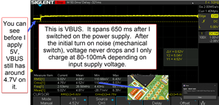
I can't figure out why this IC won't charge my battery.  If I plug it into my computer's USB 3.0 port, it charges at about 56 mA.  If I plug it into my benchtop supply (with D+ and D- shorted to each other) I can see charge current is very sensitive to input voltage.  At 4.7 Volts, it doesn't charge at all...

Input Voltage Charge Current
4.7 Volts 0 mA
4.8 Volts 12 mA
4.9 Volts 20 mA
5.0 Volts 50 mA
5.1 Volts 65 mA
5.2 Volts 85 mA
5.3 Volts 90 mA
5.4 Volts 100 mA
skip a few... ...
6 Volts 125 mA

I am using this in a system with a microcontroller, but I don't want to write the code for it right now. I want to use this charger in standalone mode only.  Perhaps in future revisions we'll write code for it - but not now.

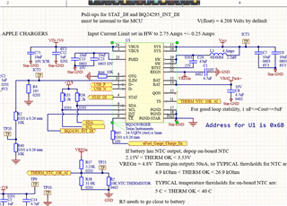
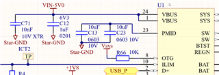
Attached is a schematic.  "nFuel_Gauge_Charge_En" comes from a fuel gauge IC.  It's pulling Charge Enable (pin 9 of the BQ24295) low as it should to enable charging.

TS pin is reading 3.04 Volts, which corresponds to 20 degrees C (it's very accurate).  The divider is there to potentially connect to a buffer to read temperature, but it's not being used right now.

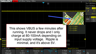
Vin-5V0 is 5.15V and again, charging is happening at about 80 mA

VREGn is reading 5.08 Volts. 

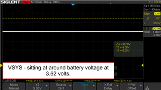
Vsys is reading 3.73 Volts, and my Lithium ion battery is reading 3.62 Volts.

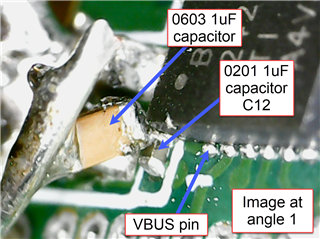
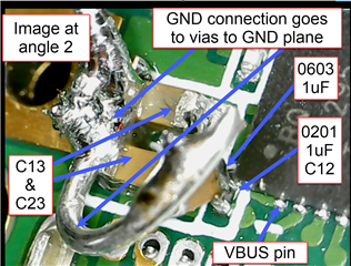
Star ground is at the pad under the IC.

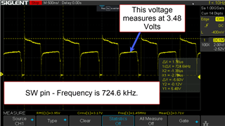
the STAT pin is low - so it thinks it's charging.  But WHY SO LOW?

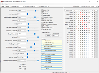
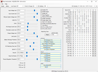
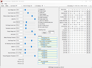
I don't have a way to read any registers.  How can I increase charging current?

  • I also want to mention that I removed the USB source, and applied a current limited source across VbatPack+ and GND, and it charges the battery at whatever my current limit is set to on my benchtop supply. This is just to show the issue is from the battery charger IC (BQ24295), and not my battery safety circuit or fuel gauge.

    As you can see from my schematic snippet, I have the battery safety circuit bypassed for now to test the battery charger IC.

  • Is somebody able to provide some insight on this?  What can I do to make the charge current go up?  Please help as soon as possible.

  • Hi,

    Please visit https://e2e.ti.com/support/power-management/f/196/t/878463 for BQ2429X: Schematic Review and PCB Layout Design Tips and https://e2e.ti.com/support/power-management/f/196/t/875388 for BQ2419X/2429x FAQs.

    Could you please read all register values of the charger? FAQ#3 and 8.3.2.2 Dynamic Power Management on the d/s should be helpful to your questions.

    Thanks,

    Ning.

  • How can I read the register values? Is there a software tool I need to download?  Can you provide a link?

  • I was able to figure out how to read the registers.  Here is a screen shot.  I changed several of the values trying to get it to work and nothing helped.  This screen shot is how it looked immediately upon plugging it in (prior to any changes I made).

    Thanks,
    Monnie

  • I do want to mention that I tried resetting the watchdog timer and disabling it, and still the charge current won't go up.  I tried manipulating everything I could think of and still it won't go up.

    I also looked into DPM in the datasheet like you suggested and I'm not in DPM, my input voltage is around 5 Volts, no less.

  • Hi,

    GUI shows "power not good" (REG08[2]=0). Please monitor the VBUS pin voltage on a scope and check. Please see 8.3.1.4 Power Up from DC Source on the d/s for the details.

    Thanks,

    Ning.

  • As I said I manipulated all of the buttons and It didn't work.  I tried several more times after resetting that error, and the power not good fault didn't come back but charge current still didn't come up.

    I'll get a scope shot of the capacitor on the VBUS pin and post it later today.  I hope this is the issue because the solution might be as simple as increasing capacitance on the input.

  • Here are some scope shots of the VBUS pin voltage.  I added an 0603 50V 1uF capacitor and took measurements again, because I do recognize I'm using an 0201 6.3V 1uF capacitor on the board.  So the 0201 1uF capacitor is likely much less than 1uF.  There was no appreciable change.  The waveform on the scope looks the same and the charge current didn't budge.  I'll get the readout from the registers and post it after I'm done posting pictures here.

    I did notice on the scope that the voltage on VBUS, when I am not applying 5V to the pin, stays at around 4.7 volts.  You can see that in one of the scope shots here.  Does that mean the internal (MOSFET RBFET Q1) isn't working?  Is it stuck on?  Could this be ESD damage on these parts?

    First here is VBUS at startup - it shows VBUS having 4.7 volts prior to me switching on VBUS (is this OK?):

    Here is VBUS after running a while:

    Here is VBUS AC Coupled showing minimal ripple.  I pulled the ground from the other side of the board at my ground test point, so the ripple may not be coming from the battery charger but another IC - I'm not sure.

    Here is a schematic snippet showing the ref des for the caps:

    here are two shots showing the added 1uF 0603 capacitor:


    and like I said, I'll get a screen shot showing the registers again and put it in a follow up post.

  • Here is the register screen shot.  I notice it says VSYS is not in regulation.  That sounds not right.  I'll get a screen shot of VSYS and the switching node (SW pin) next.  But first, here is the register screen shot:

  • Hi,

    We will check and get back to you.

    Thanks,

    Ning.

  • Thank you.  Here is a scope shot of VSYS, and then the second shot is the SW pin:

    Thank you for your support.  I'm looking forward to getting this charger working for my customer.

  • Ah, I noticed the battery wasn't charging at all when I took those screen shots of VSYS and SW pin.  Here is another screen shot when it's charging at around 80-100 mA.  I'm not sure why it wasn't charging, but now that it is charging I took another screen shot of the registers and it now says "in DPN regulation" again.  But Vbus looks the same as before.  It's 5V and no ripple.

    anyway, here is the SW pin again now that it's charging:

    another screen shot of the registers while charging:

  • Hi,

    The GUI shows the device is in DPM regulation.

    When input source is over-loaded, either the current exceeds the input current limit (REG00[2:0]) or the voltage falls below the input voltage limit (REG00[6:3]). The device then reduces the charge current until the input current falls below the input current limit and the input voltage rises above the input voltage limit. When the charge current is reduced to zero, but the input source is still overloaded, the system voltage starts to drop. Please refer to 8.3.2.2 Dynamic Power Management (DPM) for the details.

    Please visit https://e2e.ti.com/support/power-management-group/power-management/f/power-management-forum/877725/faq-bq24192-bq2419x-schematic-review-and-pcb-layout-design-tips for BQ2419X: Schematic Review and PCB Layout Design Tips and https://e2e.ti.com/support/power-management-group/power-management/f/power-management-forum/875388/faq-bq24190-bq2419x-bq2429x-faqs for BQ2419X/2429x FAQs. FAQ#3 should also be helpful to your question.

    Thanks,

    Ning.