


Hi,
I've a variable speed generator, fixed current @ ~500mA, variable voltage. It has roughly series resistance of 3 ohm and is inductive in nature.
Voltage is related to speed which determines AC frequency. Roughly the range is about 3-80v unloaded and frequency is double, so 6-160Hz. Under maximum speed and MPPT the voltage at the hub isn't above 20v, which given current is fixed yields an absolutely saturation of 10W power.
To counteract inductance phase I switch in capacitance based on the frequency, the idea being to switch in different amounts to cover the frequency spectrum. It's not perfect but allows for less loss in the core.
What I'm struggling to find, because PFC is almost exclusively used in the context of mains power where MPPT will never be reached, is how MPPT applies for a smaller generator. Consider the following diagram where the power goes into a super-cap and then is boosted into a load. The load (say a USB device) has uncontrolled current draw, so it comes from storage with a UVLO to turn off when what it demands isn't possible.
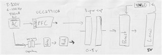
The PFC maintains a voltage but I'm fairly sure I need another step (missing on diagram) which is a current regulator into the super-cap. Assuming I go with the active PFC route using this chip or similar, then LC impedance is close to zero and so MPPT is a thevenin calculation of impedance (series and parallel resistance of the generator) and frequency. Knowing this, assuming the PFC generates a fixed DC voltage, assuming the capacitor voltage is less than this voltage, and assuming the current regulation into the super-cap is another buck in CCM mode, I should be able to -
1. Ensure losses in the generator are kept to a minimum by APFC.
2. Extract the greatest amount of power at a given speed/frequency by altering duty of the current regulator.
How's my understanding?!
