This thread has been locked.

If you have a related question, please click the "Ask a related question" button in the top right corner. The newly created question will be automatically linked to this question.

UCC21750: Regarding optional dead time control in UCC21750

Part Number: UCC21750
Other Parts Discussed in Thread: UCC21530, TLV3501

Dear sir,

Good morning.

We are using UCC21750 and UCC21530.

UCC21530 has optional dead time control DT where as we couldn't find any optional dead time control in UCC21750 in hardware.

Kindly suggest how to give dead time in output gate pulses in UCC21750.

Kindly guide and suggest.

Waiting for your reply.

Thank you,

Girish Kantharaju

  • Hi Girish,

    Since the UCC21750 is a single channel driver the dead time with the other gate driver in a half bridge configuration is handled external to the device. This can be done through the software controlling the PWM signals into the drivers.

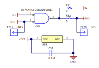
    For additional protection you can also implement additional logic components to prevent shoot through events. An example of this can be found in the UCC217xx evm User Guide. This EVM uses a CMOS logic AND gate (SN74AHC1G08QDBVRQ1) to prevent from having overlap between between the high and and low side PWM signals. In this example when both IN+ input signals for low side and high side turn ON the AND gate will make the IN- inputs high as well to disable the drivers.

    Let me know if there's any additional questions.

    Best regards,

    Andy Robles

  • Dear Andy Robles,

    Good morning.

    Thank you for your reply.

    Since the UCC21750 is a single channel driver the dead time with the other gate driver in a half bridge configuration is handled external to the device. This can be done through the software controlling the PWM signals into the drivers.

    As we are simulating in TI pspice the dead time adjustment in ucc21530 comes in handy.

    But where as in UCC21750 we can't give dead time as its single channel driver as you said.

    In simulation we are comparing triangular waveform(1V,50KHz) with reference sine wave(1V,50Hz) in TLV3501 to get sine PWM.

    So here we are finding difficulty in adding dead time in simulation.As we are dependent on circuits to provide dead time.

    Is it possible to insert program in TI pspice so that we can provide dead time to PWM pulses.

    If any software help is not possible then  how to do it in circuit/pspice settings to create dead time in pwm generated by comparing triangular waveform(50kHz) and sine wave(50Hz).

    Thank you,

    Girish Kantharaju

  • Hi Girish,

    Are you sending a signal into both IN+ and IN- or is on of the inputs constant?

    Would you be able to share the input portion of your schematic?

    Best regards,

    Andy Robles

  • Hi Andy Robles,

    We are not sending signal into both as constant.

    Previously we tried give complementary signals but now we are giving signals to

    IN+ only and IN- is tied to ground.

    Thank you for your response.

    I will share you details by the end of the day.

    Thank you,

    Girish Kantharaju

  • Hi Girish,

    Thank you for the response. I'll be waiting for the details.

    Best regards,

    Andy Robles

  • Closing this thread as discussion continued over E2E message feature.