


Hi All,
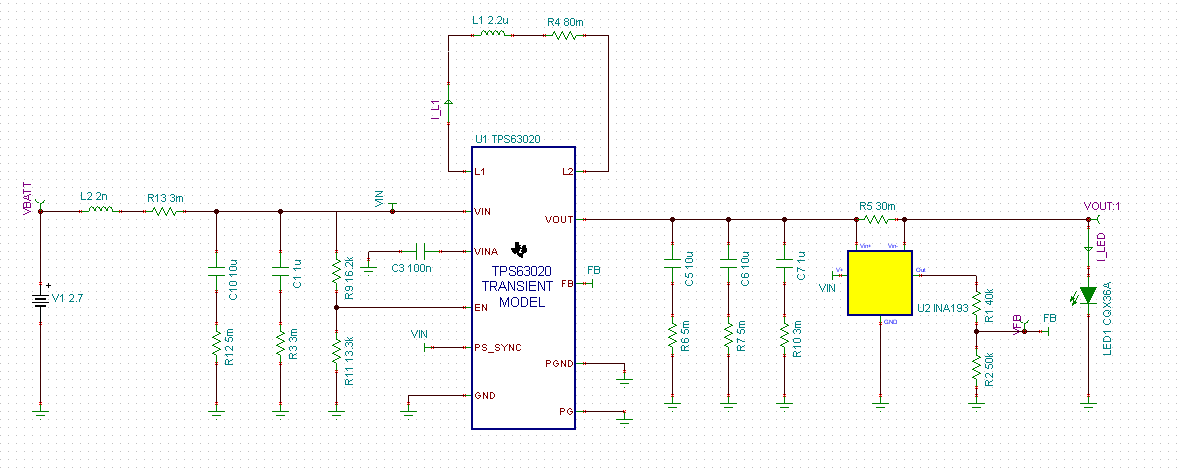
I am currently designing a LED driver using the TPS63020, and I am encountering some issues when simulating the TINA spice model. The TPS63020 seems to develop large output ripple when driving a high-current LED. The LED draws 4.5V at 1.5A, and power is supplied from a single Li-ion cell (2.7-4.2Vin). The output needs to be current regulated, so I added the INA193 current sense amplifier as described in pages 3-4 of the article "Different Methods to Drive LEDs Using TPS630xx Buck-Boost Converters". Here is my schematic diagram:
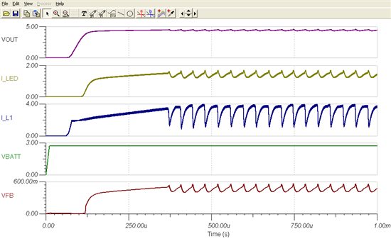
When I attached the LED to the output, the TPS63020 output became unstable and ended up with nearly 500mA of ripple current going into the LED. This amount of ripple seems unusually large and exceeds the maximum ratings for the LED. Interestingly, the simulation works fine when driving a resistive load at the same voltage and current. However, when I replace the resistor with a LED, the output becomes unacceptable.
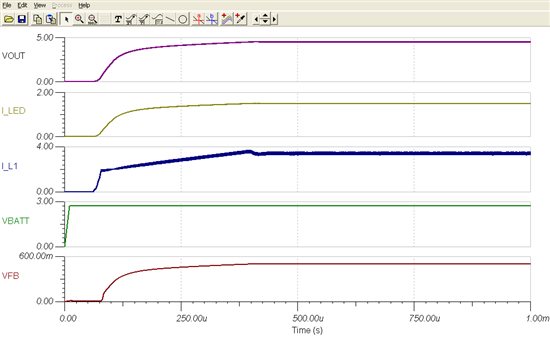
Waveforms when driving a 3Ω resistor:
Waveforms when driving the LED:
So far I've tried the following without success:
- Increasing input voltage (2.7v, 3.6v, 4.2v)
- Varying the inductor value (1.5u, 2.2u, 3.3u, 4.7u)
- Increasing output capacitance (With about 65uF of capacitance, the ripple suddenly disappeared. However, this is more capacitance than I would like to use due to PCB space constraints)
- Adding 0.1uF bypass capacitor to INA193 V+ pin
- Adding 1nF bypass capacitor to INA193 output
I have attached the simulation waveforms along with the TINA-TI model. Any help would be appreciated.
Thank you,
Daniel Kuo
