This thread has been locked.

If you have a related question, please click the "Ask a related question" button in the top right corner. The newly created question will be automatically linked to this question.

TPS65070: Li-SOCL2 battery

Part Number: TPS65070
Other Parts Discussed in Thread: TS5A23159

Good day,

My customer is using TPS65070 as a power supply for their current device. The power supply is either from a Li-Ion battery (or Li-Pol), or from USB.

Now they have the new task to run TPS65070 from a Li-SOCL2 battery (for example, SAFT LS 14500) - its voltage is 3.6V. They turned off the charging function in the device, which is planned to be used with a battery.

The problem is that TPS65070 almost never starts-up correctly when powered from the battery. Perhaps the fact is that the maximum current at the start exceeds the limitation 15 mA. Perhaps the problem is with internal logic of the TPS65070. The datasheet says that it is possible to start-up the device at 3.6V.

If they start-up the device from USB firstly, then the device works fine from the battery.

Is it possible to use Li-SOCL2 battery with TPS65070? Is there a schematic solution for this power supply option?

Thank you!

Daria

  • Hi Daria,

    I do not believe we have an available reference design for TPS65070 in any (including) a BAT only use-case. However, this PMIC should be able to start up should it be seeing either AC, USB, or BAT power. Could you include scope shots of PB_IN, PB_OUT, USB, and BAT for both scenarios? Could you also provide your schematic? 

    Best,
    Emily

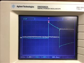
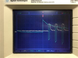
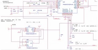
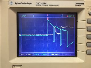
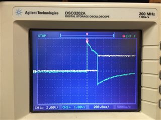
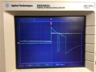
  •     I attached the part of the schematics and scope shots.


    Comments from the customer:


    1. About the part of the schematics that generates the PB_IN signal. In TPS6507х there is a safety timer. If the PB_IN signal is kept at state 0 for more than 15 seconds, then all the TPS6507x settings that are programmed there via I2C will be reset to their default settings. In their system, this cannot be allowed, since they step-down the voltage from 3.3V to 2V.


    That is why they use TS5A23159 and WatchDog timer TPS3823-33. This scheme once in 2 seconds generates the pulse on PB_IN signal, so that the safety timer inside the TPS6507x will never be triggered. They use this solution for a long time.


    1. Scope 1 – an example of the correct start-up of the device (compared a start from a Li-Ion battery with a capacity of 1000mAh , nominal voltage 3.7V, in fact, it is charged up to 4.1V, and a SAFT LS 14500 Li-SOCl2 battery with a nominal voltage of 3.6V, an actual charge is 3.6V.

    Yellow signal - SYS

    Green signal - PB_IN.


    1. Scope 2 - an example of the incorrect start-up of the device when SAFT battery is used.

    Yellow signal - SYS

    Green signal - PB_IN.

    There are attempts to start, but they end in failure for some unknown reason.


    1. Scope 3 –

    Yellow signal - AVDD6

    Green signal - PB_IN.


    А single attempt at an unsuccessful start did not affect the level of the AVDD6 signal (in contrast to the SYS signal, which drops to 0).


    All diagrams are synchronized from the moment the battery is turned on.


    There is a drop to 0 of the SYS signal, associated with the inability to supply current from the battery at the start of the TSP6507x, but I would like to get an answer whether this is so or not.

  • Hi Daria,

    My apologies, didn't mean to hit "TI Thinks Resolved." It looks like when you use a higher BAT, the system starts up as expected. Could you connect a power supply to the BAT and toggle between 3.6V and 3.7V, etc, + .1V while reading what the PMIC regulator inputs are seeing on a scope shot? Could you also re-attach the image of the schematic? It's far too small to make out anything from what I can see.

    Best,
    Emily

  • Scope 4 - the device started from a battery (SAFT) with a voltage of 3.58 V. The start took place not immediately, but after some attempts.

    I constantly see a situation where there are countless attempts to start-up, but not a single one successful.

    Scope 5 - the device started from a battery (Li-Ion) with a voltage of 3.71 В. The device has been successfully started-up.

    Yellow signal - SYS

    Green signal - PB_IN.

  • Hi Daria,

    Thank you for the scope shots. From what I can see, it seems the PMIC is not seeing a stable enough input supply on BAT in order to sustain a successful start up. I see from the part of the schematic that a 10uF cap is terminated off of SYS. I recommend placing this 10uF cap directly on BAT and seeing if this improves start-up. 

    Best,
    Emily