This thread has been locked.

If you have a related question, please click the "Ask a related question" button in the top right corner. The newly created question will be automatically linked to this question.

TPS73801: Overshoot

Part Number: TPS73801

Hi team,

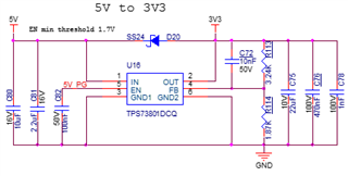
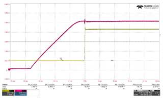
TPS73801DCQ here C72=10nF.

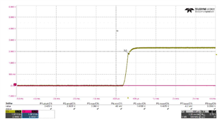
Then the 3.3V curve shows like below,there is a overshoot (3.6V maxium)

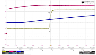
If i change the value of C72, when C72=100nF, overshoot will reach 4V maxium  (3.3Vtyp).

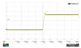
I change the value of C72,  when C72=33nF, overshoot will become to a ditch .

So i am confused about how this happen. Maybe the power on load of TPS73801DCQ is too large?

I change the value of the output capictor c75,but there is no significant use.

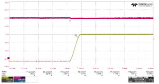
So i change the ic to TPS73701, then there is a good startup curve.

1、I want to know how can i debug TPS73801DCQ, then i can get a satisfied startup curve?

2、What is difference between TPS73801MDCQPSEP and TPS73801DCQ? Can TPS73801MDCQPSEP improve?

  • Hello,

              If the ramp rate of VIN voltage source can be controlled, then slowing the ramp rate would give the LDO control loop more time to respond and the VOUT startup ramp would be more smooth. Increasing the input capacitor (C80, C81) would help in a similar way and make the VOUT ramp smooth. TPS73801MDCQPSEP and TPS73801DCQ would be very similar to each other in performance of Electrical characteristics. The SEP version has packaging suitable even for applications in Space and can withstand very high radiation levels. Thanks!

    Regards,

    Srikanth 

  • Purple curve is NET_5V, Yellow curve is NET_3v3.

    NET_5V has 200uF capacitor, i think it is enough . But the overshoot exists.

  • Hello,

             200uF is a substantial cap. Could you provide us the input current scope shot along with the VIN and VOUT? Could you also increase the cap on the enable pin or slow down the ramp rate of the enable pin voltage and verify the overshoot? Thanks!

    Regards,

    Srikanth

  • Hello,

            Following up from the post above, the input current scope shot would help determine if the part has hit current limit during startup. If the part hits current limit during startup, overshoot will occur. Reducing output capacitors is one way to reduce this inrush current and prevent the part from hitting current limit. This is likely the reason why reducing C72 helped reduce the magnitude of the overshoot. Could you revert back to the original input caps and reduce the output cap to 10uF and verify if overshoot occurs?

            Another reason for overshoot to occur is if VEN has reached the threshold ON voltage before VIN has reached a sufficiently large value to keep the part out of dropout. Sequencing the signals such that, VIN has reached desired value before providing the Enable signal is another way to reduce overshoot. Having a high VIN slew rate will also help accomplish the desired reduction in overshoot.

            In my earlier response I recommended that the VIN slew rate be reduced or CIN be increased, this is not strictly accurate, and I apologize for this. Please try reducing output cap and/or sequence the signals so VEN is provided after VIN and verify if overshoot goes away. It would help us to see scope shots of VIN, VOUT, VEN and Input current. Thanks!

    Regards,

    Srikanth 


  • Hello,

    This LDO circuit is used in real assembly pcb,then i measure the curve

    purple curve:5V; yellow curve:3v3;blue:en     en is about 0.5V, then 3V3 begins

    Then i delete output capcitor C75=22UF, but i cannot delete all the capacitor on this assembly pcb.

    The curve (C75=NP) is same as the original curve (C75=22UF).

    In fact,  i have increased C75 value, then the ditch will become to step.

    I will change TPS73801 to TPS73701 to solve this problem.

  • Hello, 

             Thanks for letting us know, I hope TPS73701 satisfies all the requirements of your application.

    Regards,

    Srikanth