This thread has been locked.

If you have a related question, please click the "Ask a related question" button in the top right corner. The newly created question will be automatically linked to this question.

UCD90120A: About UCD90120A Firmware confirguration

Part Number: UCD90120A

Two questions:

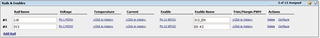
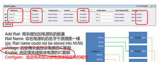
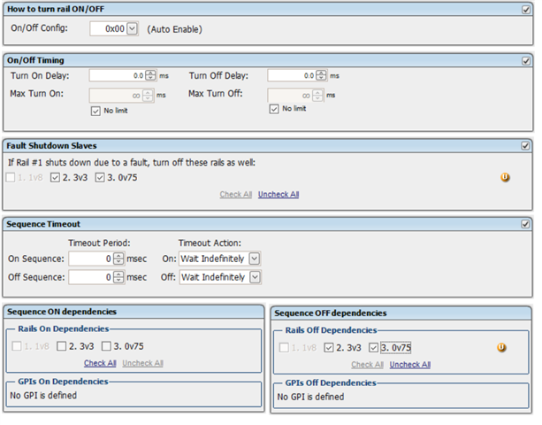
1. Rail Configuration: On/Off Config:  Control Pin Only

    Q: i didn't find where i can set the control pin or how can i set the control pin?

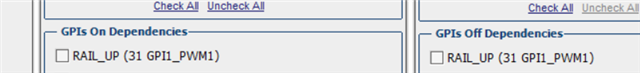
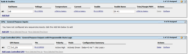
2. Rail configuration: GPIs On Dependencies and GPIs Off Dependencies

    Q: Is the GPIs is turned on/off when the power rail is ready? or is the power rail turned on/off when the GPIs is high/low?

  • Hi

    The control pin is a input signal to the device and is generated outside the UCD90120A. if you use the USB-TO-GPIO dongle, you can use the GUI to control the PMBUS_CTRL pin. Go to the Monitor Tab, there is control option: Control Line(USB) , click the HIGH or LOW to change the sigal

    I did not get your 2nd questions. GPI has two states inside the chip: ASSERTED or DEASSERTED. When the GPI is used for dependencies,  the ASSERTED state means ON dependencies and DEASSERTED means OFF dependencies. 

    Regards

    Yihe

  • Thanks for your feedback

    1. So the control pin doesn't an actual pin, it's a software command, right?

    2. In the Rail Configuration, what the GPIs On dependecies and GPIs Off Dependencies mean? For example(refer the below screenshot), what is the relationship between the rail and the GPI (RAIL UP). Will the rail be powered up when the RAIL_UP(GPI)  is high if I select the RAIL UP in the GPIs On Dependencies? Or, Will the rail be powered off when the RAIL_UP is off if i select RAIL_Up in the GPIs off Dependencies? 

    One more question:

    3. The 3v3_EN will be high when the 1v8 rail is ready, then the 3v3 rail will be powered on(like below screenshot). However, i find the 3v3 rail is still on when 1v8 rail shut down, even i set turn off 3v3 if 1v8 shuts down. How do i set 3v3 rail on and off depending on 1v8? The 3v3 will powered on when 1v8 is ready and the 3v3 will be off when 1v8 shuts down.

  • Hello

    PMBUS_CTRL is a physical pin. in order to help customer test, this pin is connected to the USB-TO-GPIO dongle which can be controlled by GUI

    You can refer the quick guide below to understand how the device work.

    Basically, the dependencies is the condition to check and it does not initialize the POWER ON or POWER OFF action.

    The power on or up is from the setting of ON/OFF_CONFIG.

    6215.UCD90xxx 简易使用手冊.pptx

    Regards

    Yihe

  • Thanks for sharing the user guide!

    But there is a conflict about power enable in the Configuring Rails. 

    1. In the Fusion Digital Power Designer document. The enable pin is an output signal to enable and disable the downstream power supply.

    2. In the user guide you provided. The enable pin is output to enable and disable itself.

    so, which one is correct?

    Thanks

  • Hi

    They are the same, both said that the ENABLE is to control the Power supply.

    Regards

    Yihe

  • My understanding is that Fusion Digital Power Designer document indicate the enable pin enable next power rail, but user guide indicate the enable pin enable itself. so, i want to figure out that.

    By the way, I still don't know how to use the control pin. Yes, i can control the PMBUS_CTRL pin by USB-TO-GPIO dongle. However, how do i control PMBUS_CTRL pin in a real usage? Is the PMBUS_CTRL pin controlled by the PMBus conmmand in the real usage? 

    Thanks

  • Hi

    PMBUS_CTRL is a signal from outside of the UCD, it can be GPO from your host or FPGA.

    This can not be controlled by PMBus.

    if you do not have a PMBUS_CTRL signal in your design, you shall not use it.

    Regards

    Yihe

  • Is it a GPI that i configre like below picture?

  • Are the PMBUS_CTRL GPIs or enable pins that i set?

    Thanks

  • Which pin is control pin of power rail? Is control pin the rail enable pin or GPIs? For example(refer below picture), GPIO1 is 1v8 rail control pin, right? and  GPIO2 is 3v3 rail control pin, right? Would you please help to give a example?

    Thanks

  • Hi

    control pin is dedicated pin defined in the data sheet which pin 28.

    The GPIO1 is the pin to control you power-supply's ENABLE signal. 

    if you have rail1's ON/OFF_CONFIG set to CONTROL PIN Only. then the output of GPIO1 is controlled by the PMBUS_CTRL pin.

    Regards

    yihe

  • Thanks Yihe feedback. I see the control pin usage.

    Another question: Do these enable pins enable next power rail or enable itself? Fusion Digital Power Designer document indicate the enable GPIOs to enable downstream power supply. My understanding the GPIO enable next power rail. Like below picture, the Pin4 GPIO1 Rail #2 eanbled signal, is it right?

    Thanks 

  • Hi

    The ENABLE is designed to enable itself so that we can control it via the monitoring its own voltage.  GPIO1 is to enable rail#1.

    Regards

    Yihe

  • Thanks for your answer! It's very helpful!

    Last question: How to set that turn off slave rails if the rail shut down? Below is what i do.

    1. Set Rail#1 Fault Shutdown Slaves Rail#2, Rail#3 as below screenshot.

    2. Set Rail#1 Fault Response Shut down immediately.

    3. Disconnect Rail#1 enable output GPIO1 or deassert Rail#1 enable output GPIO1.

    4. The Rail#1 shut down but Rail#2 and Rail#3 are still on.

    Thanks

  • Hi

    Do you see the orange "U"? Have you clicked the "write to hardware" button to let the changes accepted by devices?

    one more thing to check: does rail2 and rail3 have any turn off dependencies? if they do, make sure that the dependencies are met so that rail 2/3 can be off.

    Regards

    Yihe

  • Yes, i confirmed i wrote to hardware. The screenshot is only an example. The below are what i do.

    1. If 1v8 rail voltage is set lower than 1.5v(triger under voltage fault), the 1v8 rail shut down and 3v3 and 0v75 rails turn off too.

    2. However, If 1v8 rail eanble signal is disconnected or is deasserted, the 3v3 and 0v75 rails are still on even 1v8 voltage is 0.

    How do i deal with the case2?

    Thanks

  • Hi

    Did you get the UV fault on the 2nd case? UV is only reported if the voltage drops below UV_THRESHODL after reaching POWER_GOOD threshold?

    Regards

    Yihe

  • Hi

    Yes, the case2 setting is same as case1 setting. Do you mean case 2 won't report UV fault? The slave rials(rail2 and rail3) won't be turned off if rail1 enable signal is pulled down or Rail1 broken due to some errors, right?

    Thanks

  • Hi

    No, what I mean is whether the device report UV fault on the 2nd case. if not, rail2 and 3 would not be off.

    As said in the previous reply. UV fault is reported only if both conditions are met:

    1. the rail is ON(on/off_Config is met to turn on, any turn on dependencies are met to on)

    2. the rail is below it is UV threshold after reaching its POWER_GODO threshold 

    how do you pull down the EN signal.

    Regards

    Yihe

  • Hi 

    I added the switch on the EN signal, so i can control the EN. I turn off the EN after all power rails are ready. Then, only Rail #1 shut down, Rail #2 and Rail #3 are still on. Is that normal?

    By the way, what do you mean "if not, rail2 and 3 would be off."? Do you mean rail2 and 3 would be off if UV fault report?

    Thanks

  • Hi

    Could you confirm whether Rail#1 has reported UV fault or not when turn off the EN?

    please provide a snapshot of the system monitor tab.

    regards

    Yihe

  • Hi 

    Where can i see the UV fault report?

    Thanks