This thread has been locked.

If you have a related question, please click the "Ask a related question" button in the top right corner. The newly created question will be automatically linked to this question.

LMG1210: Periodic cuts on output signal in 20MHz half-bridge application

Part Number: LMG1210


Hi,

I am using LMG1210RVRR component to create a 20MHz output for an actuator.

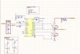
I followed the design of the LMG1210EVM evaluation board (Figure 3).

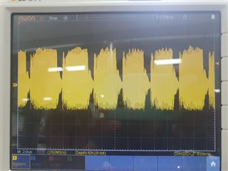
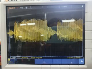
When looking at the output signal I can see a periodic cut in the signal (each 3us) (Figure 1 and 2).

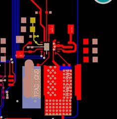
I don't know if it can come from the bootstrap diode which has 25ns of Trr in my case, or an issue in the layout or maybe heat issue with overtemperature security ?


Do you have any idea what can cause those cuts ?

Thank you.

  • Hi Aly,

    Thank you for your question.

    The schematic you shared doesn't display the value of the VCC capacitor C11. We recommend this capacitor to be at least 10 times bigger than the bootstrap capacitor. You are using 0.47uF for the bootstrap cap, so you can use 10uF for C11.

    For high frequency applications like yours we recommend using a schottky diode for the bootstrap diode. You can look at the one listed in the BOM of the LMG1210 EVM (BAT46WJ). 

    To check that you are not exceeding the junction temperature that the device is able to handle, you need to calculate the power dissipation of the device. Please see the device datasheet, section 8.2.2.5 Computing Power Dissipation. Once you calculate the power dissipation, you can use this formula:

    Tj = (P * RθJA) + Ta

    where Tj = Junction temperature; RθJA = Junction-to-ambient thermal resistance; Ta = ambient temperature

    If the calculated Tj is above the recommended junction temperature specified in the datasheet of the device (125C), then you are exceeding the power that the device can dissipate. 

    Alternatively, you can use this "maximum switching frequency" calculator to estimate the maximum switching frequency you can use based on your application:

    https://e2e.ti.com/support/power-management-group/power-management/f/196/t/1025075

    Best regards,

    Leslie

  • Thank you for your help.

    The main issue was the lack of external gate resistors. I manage to figure it out with the maximum switching frequency calculator.

    Best regards,

    Aly

  • Hi Aly,

    That's great! I'm glad you were able to solve your issue and thanks for the follow up. Feel free to create a new thread if you need further help. 

    Regards,

    Leslie