This thread has been locked.

If you have a related question, please click the "Ask a related question" button in the top right corner. The newly created question will be automatically linked to this question.

BQ76942: External temperature sensor polynomial coefficients and tuning

Part Number: BQ76942
Other Parts Discussed in Thread: BQ76952, BQSTUDIO, TIDA-010208

Hello,

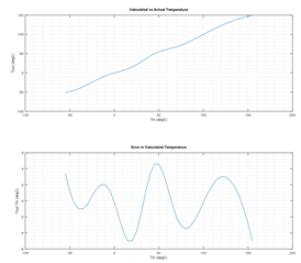
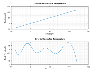
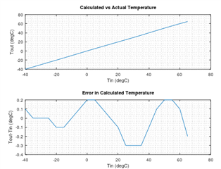
We're attempting to use the internal temperature protection on the BQ76942 protection IC. The A and B coefficients were configured using the excel spreadsheet provided in the technical documentation for this chip. The issue we're having is that the reported temperature does not perform well at reasonably low and very high temperatures. The temperature is objectively verified using a separate well calibrated digital temperature module. 

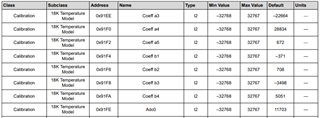
We've configured the internal pullup to 18kR, and the nominal resistance of the thermistor is 10kR at 25 degrees Celsius. We've tried using both the 18kR internal model, as well as the custom temperature model, both perform virtually identically. The Adc0 was empirically verified, and the Rc0 was selected using the defined formula in the reference manual of the BQ76942. In ice water (about 4 degrees Celsius), the thermistor model returns 17 degrees Celsius, and in hot water (80 degrees Celsius) the thermistor model reports 84. The model does seem to perform well within the range of 20 to 70 degrees.

Any insight into how we could improve the performance of the temperature model would be much appreciated!

Thanks,

-Alex

  • Hi Alex,

    The spreadsheet tool does not always generate the most accurate results. I have an internal tool. If you send me the R/T table for your thermistor, I can generate new coefficients to see if it improves the performance. 

    Eventually we will release the improved tool to the product folder. 

    Best regards,

    Matt

  • Hi Matt,

    Thanks for getting back to me.

    Here is the R/T chart for our NTC thermistor.

    Celsius R
    -55 963000
    -50 670100
    -45 471700
    -40 336500
    -35 242600
    -30 177000
    -25 130400
    -20 97070
    -15 72930
    -10 55330
    -5 42320
    0 32650
    5 25390
    10 19900
    15 15710
    20 12490
    25 10000
    30 8057
    35 6531
    40 5327
    45 4369
    50 3603
    55 2986
    60 2488
    65 2083
    70 1752
    75 1481
    80 1258
    85 1072
    90 917.7
    95 788.5
    100 680
    105 588.6
    110 511.2
    115 445.4
    120 389.3
    125 341.7
    130 300.9
    135 265.4
    140 234.8
    145 208.3
    150 185.3
    155 165.3
  • Hi Alex,

    Here are the best coefficients for this thermistor for the -55 to 155 range. It is difficult to get great accuracy over the whole range.

    A1-A5: -8192 -4096 20479 12287 4095   

    B1-B5: -24025 23828 -8742 4503

    ADC0 = RC0 = 11703

    As shown below, it does have up to 5C error over the range.

    I also tried a smaller range to see if I could improve the accuracy. This gets much better accuracy over a -40 - 120C range, but it would get worse accuracy at extremes of -55C and 150C.

    A1-A5: -21846 27306 -10923 32767 5461  

    B1-B5:   -31395   23656   -8209    4298

    ADC0 = RC0 = 11703

    Best regards,

    Matt

  • Hi Matt,

    Thanks for this. Could you provide another set of coefficients that over-fit on the range of -40 to 65?

    -Alex

  • Also, we just verified that the -40 to 120C fit still performs poorly at low temps. At 4C the protection IC returns an estimated value of 16.8C.

  • Hi Alex,

    Here are the coefficients for -40 to 65:

    A1-A5: -10923  -10923   -5462   32767   10922

    B1-B4: -2515   5020  -4224   3808

    For your testing, I assume you are using the 18k setting and the 18k temp model?

    Matt

  • Hi Matt,

    Thanks again for these plots. Unfortunately we're still having issues with lower temperatures. It seems to be consistently off by 12C. We've configured the BQ to the 18kR pull-up and the 18kR model when writing the coefficients. I've confirmed that the ADC is not saturating, albeit when converting from counts to voltage it doesn't exactly match up with what would be expected from the resistances.  

  • Additionally, here is the datasheet for the thermistor we are using. We're using the 8016 R/T curve for a 10kR thermistor.

    www.tdk-electronics.tdk.com/.../NTC_Mini_sensors_S861.pdf

  • Hi Alex,

    How are you reading the measurement from the BQ76952? Are you using the direct commands like 0x70? Can you share your register settings?

    Matt

  • Hi Matt,

    We are indeed sampling the 0x70 (TS1) register, which we convert from deci-Kelvin to Celsius. We have configured the TS1 configuration register to use the 18kR pullup and model (0b00001011)

  • Can you share the complete register settings? If you are connected to BQStudio, you can export a .gg.csv file from the Data Memory screen. 

  • This is through our own MCU, not on the dev kit. I can provide whatever register settings you think would be useful information.

  • Maybe you can share the code where you write your configuration registers. I am mostly interested in the parameters below.

  • We currently have the temperature offsets set to 0.

    Here is the block that configures the coefficients and the ADC0 for the 18k model, as well as the config register for TS1

    //Custom Temperature Model Coefficients
        data.length = 2;
        data.value.int16Val = -10923;
        BQ76942_Data_Memory(&hspi1, C18K_TEMP_COEFF_A1, &data, &error);
        data.value.int16Val = -10923;
        BQ76942_Data_Memory(&hspi1, C18K_TEMP_COEFF_A2, &data, &error);
        data.value.int16Val = -5462;
        BQ76942_Data_Memory(&hspi1, C18K_TEMP_COEFF_A3, &data, &error);
        data.value.int16Val = 32767;
        BQ76942_Data_Memory(&hspi1, C18K_TEMP_COEFF_A4, &data, &error);
        data.value.int16Val = 10922;
        BQ76942_Data_Memory(&hspi1, C18K_TEMP_COEFF_A5, &data, &error);
        data.value.int16Val = -2515;
        BQ76942_Data_Memory(&hspi1, C18K_TEMP_COEFF_B1, &data, &error);
        data.value.int16Val = 5020;
        BQ76942_Data_Memory(&hspi1, C18K_TEMP_COEFF_B2, &data, &error);
        data.value.int16Val = -4224;
        BQ76942_Data_Memory(&hspi1, C18K_TEMP_COEFF_B3, &data, &error);
        data.value.int16Val = 3808;
        BQ76942_Data_Memory(&hspi1, C18K_TEMP_COEFF_B4, &data, &error);
        data.value.int16Val = 11703;
        BQ76942_Data_Memory(&hspi1, C18K_TEMP_ADC0, &data, &error);
        // Thermistor Configs
        data.length = 1;
        data.value.uint8Val = 0b00001011; // Enable thermistor input, use 18k model
        BQ76942_Data_Memory(&hspi1, TS1_CONFIG_ADDR, &data, &error);
        BQ76942_Data_Memory(&hspi1, TS3_CONFIG_ADDR, &data, &error);

  • Thanks. I assume you write all of these while in CONFIG_UPDATE mode? The TS1 Temp Offset is not written, correct? Are you able to read these back to confirm they are written correctly?

    I am just trying to think of possible reasons the temperature error would be so high. I haven't seen anyone else report this large of an error. Do you have a different type of thermistor you can try?

  • Yes, this is just a block from the section that's wrapped in CONFIG_UPDATE mode.

    We can verify the offset isn't written, but it doesn't seem to be offset at the nominal temperatures.

    We could potentially try a different thermistor, albeit this would not be the preferred solution.

    One thing we are currently doing is sampling the 32-bit ADC value provided by the protection IC, and using our own curve fit to calculate the temperature. Our curve is a 2 coefficient log fit, and calculates the temperature within 4 degrees without being over-fit.

  • Hi Alex,

    Can you capture the ADC counts for each temperature along with the calculated temperature value returned by 0x70? I can run the raw counts through our tool as a secondary check. I can also look at the counts to make sure they match with the ideal values expected for this thermistor at each temperature.

    Matt

  • Hi Matt,
    Here is a table showing the measured TS1 Raw 32-bit ADC Counts from DASTATUS6() at each temperature (5 C apart), along with the temperature calculated by the TS1 0x70 command using the configurations listed above.

    Temperature (C) 0x70 Temp (0.1 K) Converted to C Measured ADC Count
    85 3500 76.85 423628
    80 3487

    75.55

    464014
    75 3451 71.95 516198
    70 3420 68.85 563821
    65 3372 64.05 642005
    60 3338 60.65 704669
    55 3295 56.35 801666
    50 3240 50.85 916008
    45 3191 45.95 1043905
    40 3142 41.05 1194255
    35 3102 37.05 1327528
    30 3067 33.55 1497400
    25 3020 28.85 1651612
    20 2989 25.75 1805898
    15 2956 22.45 1973195
    10 2937 20.55 2076696
    5 2900 16.85 2280277
    0 2892 16.05 2329325

    Thanks,

    Ryan

  • Hi Ryan,

    The ADC count measurements are interesting. They do not seem to match with the voltages I would expect from your thermistor's resistance table. See the theoretical ADC codes in the right-most column below. These are the voltages and ADC counts we would expect based on your thermistor. Is there any chance the thermistor part number is different from the datasheet Alex sent? 

    One other thing we could check is to see if the value of the internal 18k pullup resistor is way off. If you read the ADC count at room temperature with a 10k resistor connected, it should read something close to 1797559. 

    Temperature (C) 0x70 Temp (0.1 K) Converted to C Measured ADC Count R for thermistor temperature Theoretical voltage for R Theoretical Code
    85 3500 76.85 423628 1072 0.101174497 282904.3973
    80 3487 75.55 464014 1258 0.117582303 328783.9505
    75 3451 71.95 516198 1481 0.136841025 382635.2379
    70 3420 68.85 563821 1752 0.159659781 446441.1062
    65 3372 64.05 642005 2083 0.186695215 522037.6576
    60 3338 60.65 704669 2488 0.21858649 611212.1253
    55 3295 56.35 801666 2986 0.2561136 716145.53
    50 3240 50.85 916008 3603 0.300208304 839443.2613
    45 3191 45.95 1043905 4369 0.351566901 983052.305
    40 3142 41.05 1194255 5327 0.411051571 1149383.499
    35 3102 37.05 1327528 6531 0.479222209 1340002.418
    30 3067 33.55 1497400 8057 0.55657213 1556288.475
    25 3020 28.85 1651612 10000 0.642857143 1797558.857
    20 2989 25.75 1805898 12490 0.73735651 2061798.24
    15 2956 22.45 1973195 15710 0.838860872 2345625.008
    10 2937 20.55 2076696 19900 0.945118734 2642743.523
    5 2900 16.85 2280277 25390 1.053284167 2945195.996
    0 2892 16.05 2329325 32650 1.160315893 3244478.395

    Best regards,

    Matt

  • Hi Matt,

    The datasheet we have is directly from the battery manufacturer, and is mostly empirically verified as well. As for the test of the pull-up resistor, I attached a 12K resistor (did not have any 10s) at 22 C, and got an ADC count of 1773997.

    Is it worth investigating the ADC calibration?

  • Ryan, 

    Can you measure the voltage at the pin with a multimeter with the resistor connected? It seems like the value is pretty far off what we should expect.

    Matt

  • Hi Matt,

    Do you mean measure the voltage over a resistor attached to the TS1 pin and ground?

  • If I measure over the thermistor we have plugged in (which is sitting at about 10kR), the voltage kinda fluctuates between 0 and 30mV

  • Hi Alex,

    The thermistor voltage is enabled once every measurement loop so that it does not use power when it is not taking a measurement. So you may need to measure this on a scope.

  • Hi Matt,

    On a scope I see a brief jump to 670mV over the resistor, with the width of the pulse being about 500us

  • Okay, that sounds much closer to the expected value. So you are getting the expected voltage across the resistor, which is good. 

  • But the ADC counts don't seem to match up with what you'd expect across the internal 18k pullup? What would that indicate?

  • Hey Matt,

    Any thoughts on this?

  • Hi Alex,

    I've been crunching the numbers trying to figure out what could be happening. When you read the ADC count directly, it is not using any of the calibration settings, so the settings for the temperature polynomial or ADC Gain will not affect the reading. The code you are reading and voltage you are seeing for the 12k are in the correct range, but not exactly what I would calculate for a theoretical value. Even if these are off slightly, it still does not explain the codes you are reading as you sweep the temperatures. For example, at 85C, you measured an ADC count of 423628 and the theoretical thermistor resistance according to your datasheet is 1.072k. Theoretically with an 18k pullup, this would result in 101.1mV across the thermistor or a code of 282904 which is much lower than the code you read. 

    That's why I was wondering if the thermistor datasheet is correct for the device you are using on your board. It seems like the ADC codes are close to theoretical near room temperature but around 33% high at hot temperature and 40% low at cold temperature. This is all before we apply the polynomial.

    Best regards,

    Matt 

  • Hi Matt,

    We reached out to our battery manufacturer who provides our sensors, and they confirmed that the data sheet is correct. I did also empirically verify the thermistor resistance at a few temperature extremas, and they seem to match the data sheet.

    Are the temperature sensor pins exposed on the dev kit? I could try and see if the same behavior exists there if you think it'll be useful.

  • Yes, you can access the temp sensor pins on the EVM. Just be sure to check the schematic in the BQ76952 EVM User Guide for the test points. TS1 and TS3 have thermistors installed on the board.

  • Hi Alex,

    Matt and I have been discussing your case, I also did more crunching on the numbers you've provided, and so far I cannot come up with an explanation for what you're seeing.

    Are you seeing the same behavior on multiple boards, using different devices, or are you mainly working with a single board?

    Were you able to do anytesting with the EVM, to try and replicate it there?

    I know you've taken a lot of data, so I hate to ask for more, but I don't know a better way to debug this further.  Here are some suggestions that may help us diagnose this more:

    Can you look closely on a scope at the pulsing behavior on the thermistor pin while it is operating?  If you have too much capacitance on the node, the slower settling behavior can affect the conversions.  We recommend limiting the capacitance at the node to < 4nF.

    In order to determine if the ADC is measuring properly, can you drive the thermistor pin with a fixed voltage and capture the raw counts data from that, sweeping the voltage from 0V to ~1.8V in a few steps.  Steps getting near to 1.8V are probably most interesting, since that would be the expected voltage at low temp, when the thermistor has a fairly large impedance.  Ideally you capture this data at room temp and at a low temp, in case there is something going on with the ADC when the die temp is low.  Also please measure the voltage of the REG18 pin during this, since the part does a ratiometric conversion using that as the supply for the thermistor and the ADC reference.  If that pin has too much noise on it, that could affect the measurements.

    While doing the ADC measurements with a voltage driven at the pin, if possible can you measure the current you sink into your driving source?  That current will let us calculate the value of the internal pullup resistor.  I back-calculated the internal pullup resistor value from the data you provided earlier, that looks as expected at higher temps, then drastically ramps up at lower temps, far above anything we've seen before.  But this will give more direct measurement of it.

    Thanks,

    Terry

  • Hi Terry,

    This is actually an excellent catch! I was not fully aware of the measurement policy so I did place 100nF capacitors in parallel with the thermistors on both our thermistor lines. We will replace these with 1nF capacitors and test everything again.

  • We removed the caps, and that made a significant difference! We were able to measure accurately all the way down to -14C. Thanks so much for the help!

    One last question we have is whether any external cap filter is recommended?

  • Hi Alex,

    That's great news! Having a smaller capacitor can be helpful to reduce noise if there are long wires to the thermistors. 470 pF is a very commonly used value - this is used in the reference design TIDA-010208: https://www.ti.com/tool/TIDA-010208 

    Best regards,

    Matt

  • Hi Matt,

    We do have these thermistors on 35cm long leads so that they can be installed inside the battery pack. Based on Terry's comment above, and with the aim of not adding another line on the BOM, I will go with 1nF for these. Let me know if you see a problem with that choice.

    Thank you so much for all your help!

    -Deniz

  • That should be okay. It is within the datasheet recommended range.