This thread has been locked.

If you have a related question, please click the "Ask a related question" button in the top right corner. The newly created question will be automatically linked to this question.

UCD3138A: Control strategy for 4 switch buck-boost converter

Part Number: UCD3138A
Other Parts Discussed in Thread: PMP21529,

hi,

I'm making 4 switch buck-boost converter using UCD3138A. I did analyze the reference design PMP21529 and I saw that it's hard switching between topologies (buck, boost, buck-boost) using interrupts (standard_interrupt.c) measuring input/output voltage. My question is is there an easier way to do this, using UCD3138A HW only, without any ARM supervision?

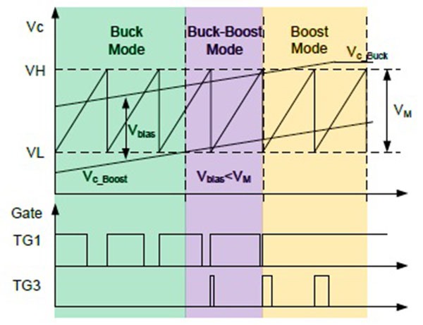
It could be done using this approach (even better with triangular mode) but it would then require adding bias to filter output, which I think, is not possible.

  • Hi Tomasz,

    Depending on your requirement it is possible to make this work on HW only or very little dependence on CPU. The tricky part is the transition from Buck to Boost or otherwise. 

    I can make a suggestion here for you to try:

    EADC0-->Filter0-->DPWM0(Buck)

    EADC0-->Filter1-->DPWM1(Boost)

    Let's say Vin >Vout then the Buck side having Q1( Main switch) and Q2 should be in control. For the boost block having Q4 and Q3(Main switch), Q4  should be almost 100% on. But that's not possible if you are using boot-strap based driver. So lets put a minimum duty of d2=5% to allow Q3 to be turned on. 

    For this to work well, you need to have two separate dutys. The d1 and d2. The only way to do this is to use two separate filters, one for buck(Filter0) and the other for boost(Filter1), both connected to Vout sensing EADC block(EADC0). Since both the filter are connected to the same error ADC, you need to have a way to allow one filter(Buck) d1 to control Vout and the other to provide a fixed duty d2=5%. 

    One way to achieve is to put a minimum and maximum duty limit for the Filter1-DPWM1 path controlling d2 to have a fixed boost duty. 

    When Vin ~Vout, d1 is almost maxing out. lets clamp d1 to 95% max. Upto this point vout control exists by buck control. When Vout begins to get bigger than Vin or when Vin begins to be smaller Vout, then you are operating at fixed duty values, d1=95% and d2=5%. 

    In order to get out of that, the max clamp on  filter1-DPWM1 path controlling d2 should be released so that d2 >5% and achieves control of the output in boost mode. Here the buck side is fixed at 95%. Meaning d1 min is also 95%. 

    So there is a buck to boost control transition involved here, and this transition can be done when d1 reaches 95%. In order to detect when d1 becomes 95%, you can use DPWM mode switching interrupt to create a fast interrupt and take appropriate actions. To be exact, when you get a fast interrupt for transitioning from buck control to boost control, you should : release d2 to be greater than 5%, set d1 min to be 95% to as to get a fixed duty of 95%.

    The reverse can also be done for boost control to buck control transition.

    I hope this give you some ideas for you to try.

    Good luck !

    Sanatan

  • thanks, for the idea. I'll check it out and compare PWM vs voltage measurement approach. I can see a potential problem that device can be in buck state but during transient state PWM goes up suggesting boost mode.

  • This PWM generations strategy can be done using cycle adjust (both in normal and triangular modes)