This thread has been locked.

If you have a related question, please click the "Ask a related question" button in the top right corner. The newly created question will be automatically linked to this question.

TPS54A20: load transient question

Part Number: TPS54A20

Hi expert, 

when operating in 2-phase interleaving mode, I'm interested in what would happen during load transient.

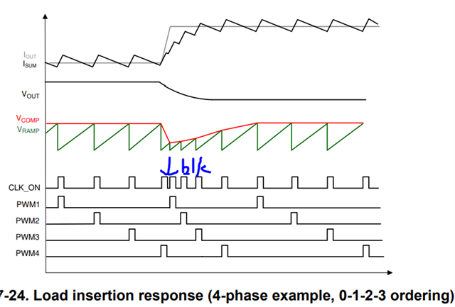
For example, when very large and high slew-rate load step-up comes, the control loop easily goes into saturation, what is the behavior of 2 phase switching? Non-linear like phase overlap, or with a blanking time between two phases?

As you know, in ACOT control, switching frequency would go up to very high when load inserts, any limitations of highest switching frequency?

  • The controller will quickly respond to large load steps by putting out on-time pulses with a higher frequency (load step up) or a reduced frequency (load step down). In this regard, it acts just like other constant on-time controllers. The high side switch on-times of the two phases will not overlap at any time and could be viewed as a maximum frequency limit (with some additional deadtime delays, etc. added around the on-times). 

  • Hi Pradeep,

    thanks for your explanation, it is the same with limitations of "blanking time" in mutli-phase applications, right?

    As datasheet didn't tell the detailed spec of this behaviors, I would like to learn how high fsw can be during large load-transient? I'm worried about this high frequency going too high.

  • Hi,

    In datasheet description section, it describes that 'an adaptive on-time control architecture provides fast transient response and accurate voltage regulation at up to 10-MHz operating frequency'.

    Only when very large and high slew-rate load step-up comes, output will be drop rapidly so that only in this narrow time duration, high fsw is implemented.

    Thanks,

    Lishuang

  • The limitation is similar but slightly different. The high side switches in the series cap buck topology should not be turned on at the same time to avoid overstressing FETs and disrupting the current sharing. So, the controller avoids this overlap of on time. There is a small blanking time/dead time between high side on-time pulses for the two phases. You could estimate the highest frequency possible based on the on-time during steady state with a small blanking time between pulses.