This thread has been locked.

If you have a related question, please click the "Ask a related question" button in the top right corner. The newly created question will be automatically linked to this question.

UCC27712: Gate Driver Selection for Motor Driver Application

Part Number: UCC27712

Hello Team,

We have come to the Ti part UCC27712dr for Our motor Control application

Want to verify few things  Before we procced to design

1)Gate driver capability to Drive the Mosfet's(3 in parallel)

2)Boostrap Diode Voltage rating 

3) You recommend to use Zener diode at LO & HO Pin 

System Parameter

System Voltage :60V

Vgs: 12V

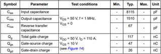
MOSFET Parameters attached the Image

No of MOSFET Parallel:3

targeting Raise time:500ns

Fsw:20khz

PFA of mosfet Data

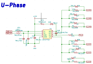
And gate Driver Schematic

Thanks

  • Hello Chaitanya,

    thank you for providing all of these details, it really helps when answering questions.

    1) Gate driver capability to Drive the Mosfet's(3 in parallel)

    If I understand correctly, you will have 3 MOSFETS in parallel on both high and low side for 6 total? To drive 3 in parallel, the gate charge is 117nc*3, which is 351nc. Divide this by the rise time (500ns) to get an estimate of the drive strength needed. In your case 351/500 = 0.7A. The part you selected is rated for 1.8A sourcing, which is above minimum and should be okay. Also, you should be careful that your FETs have the same the same trace length and width from the driver in order to ensure they turn on/off at the same time.

    2)Boostrap Diode Voltage rating 

    In the worst case, your bootstrap diode should be able to handle a reverse DC voltage of your Vbus(the voltage on the drain of your high-side FET) + VDD voltage. I am a little confused by the naming conventions you used, but if your system voltage(60V) is Vbus, and Vgs is VDD, you need at least 72V. However, you should double check that we are referring to the same voltages. Also, you should go above that number to handle transients and make your system more robust.

    3) You recommend to use Zener diode at LO & HO Pin 

    Unfortunately, I am confused by this one. In your diagram, you have what I believe are Schottky diodes on LO and HO, not Zener diodes. Zener diodes are sometimes used to create a negative voltage for driving SICFETs, but I don't know if that is what you are referring to. The purpose of those Schottky diodes is to allow the FET to sink current through that path rather than through the gate resistor. If you are referring to clamping negative voltage on the switch node, that is also usually done with a Schottky diode. 

    Lastly, I have a few comments/considerations, Firstly, why are you opting to use a 600V driver when your system is only 60V? Was that perhaps a typo? We have drivers rated in the 100V-200V range that may deliver better performance for your system. Secondly, I usually see this motor topology used with isolated drivers. The reason is that the high-side FET tends to require a high duty cycle which the bootstrap circuit cannot provide. In that case, people will use a floating power supply rather than a bootstrapping circuit. You may already be aware of this, or have a duty cycle that will not be a problem; I am just checking to make sure. If you have any additional questions, feel free to reply with more.

    thanks,

    Alex Mazany

  • Hi Alex,

    Thanks For Your Valuable Feedback.

    1)why are you opting to use a 600V driver when your system is only 60V

    Ans: We've already gone through other gate driver which are rated for 100V-200V

    consideration: i)Driver Capability for driving the FET's ii) layout complexity & Pin count  iii) unit price ( BOM cost, I think this part is little bit cheaper  than other part)

    and this particular part fits to our requirement perfectly.

    Could You please recommend Any other Part,

    2) I usually see this motor topology used with isolated drivers

    Ans: Our system max duty will not going to exceed 90%, what would you recommend for this duty cycle.

  • As long as the UCC27712 fits your needs, there is no problem with using it. It is a very cost-effective part so its not a bad choice at all. As for your second point, the 90% duty cycle is doable but can be hard to balance. You should carefully reference both this document on bootstrap circuitry selection and this one about minimum on time. The selection of these components will be critical to reaching those high duty cycles.