


Hi, I’m testing my buck converter design with the LM25117 controller
The operating conditions are
Vin = 24 V
Vout = 3,3 V
Iout = 4 A (resistive load)
fsw = 250 kHz
The design use those components
Inductor = 10 uF

Output capacitor (all the below components in parallel)
- Two 820 uF ( aluminium polymer capacitor, ESR = 11 mOhm )
- Four 10 uF 0805 MLCC
- Two 100 nF 0805 MLCC
Cout = (2 * 820 uF + 4 * 10 uF + 2 * 100 nF) = 1680 uF
I check the stability of the converter with the loop gain measurement (injection transformer in parallel with 20 Ohm) and I find
Bandwidth = 3,5 kHz
Phase margin = 97 degree
I check also the load step response and it is ok
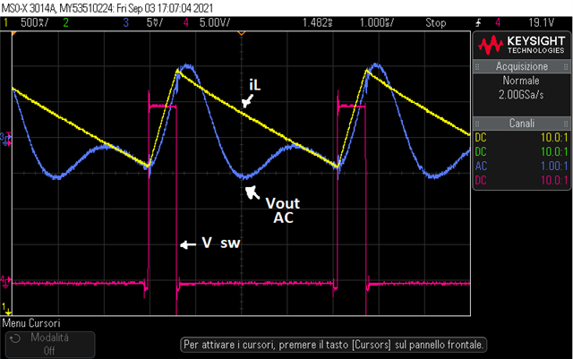
The output voltage ripple has a strange waveform that I never see before.
I post a screenshot (the output voltage ripple is take with the oscilloscope in AC coupling)
The voltage probes are used with low inductance connection (pig tail)
My questions are:
- Why the output voltage ripple has that waveform (that differs from the canonical waveform), what can be the cause?
- It may be an indication of a malfunction of the converter ?
Thanks
