Other Parts Discussed in Thread: BQ76930, , BQSTUDIO
Hello,
We're using the auto cell balancing feature that's provided by the protection IC, and are experimenting with the feature to see how well it can balance a battery. We have a 10-cell LiPo battery, where each cell can be safely charged to a maximum of 4.2V (42V battery).
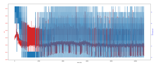
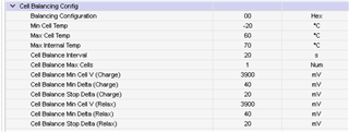
Our experiment starts with choosing a random cell on the battery, then shorting that cell to manually imbalance it. We chose a relatively safe delta of 20-26mV so that it should be relatively easy to recover. Next the auto cell balancing algorithm is enabled with the following config.
- 1 cell allowed to short
- Relaxed min delta of 13mV
- Relaxed stop delta of 10mV
After about 24 hours of balancing the the max delta hasn't really changed that much, with the max delta sitting at 21mV (as opposed to 26mV). Could we be provided some insight into what the limitations, expectations, and possible issues of cell balancing could be?
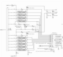
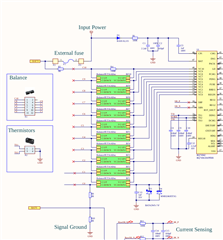
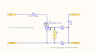
I've provided two images to parts of our schematic that depicts the individual cell balancing FET circuit, as well as the whole balance circuit in relation to the protection IC. Please analyze them and let us know if there are any glaring issues with them, but for the most part they were taken from the reference design provided for this chip.
FET circuit
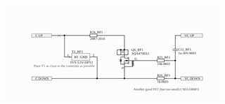
Balancing Circuit
