This thread has been locked.

If you have a related question, please click the "Ask a related question" button in the top right corner. The newly created question will be automatically linked to this question.

TPS6594-Q1: Two questions about unused BUCK FB pin

Part Number: TPS6594-Q1

Hi Team,

Here are two questions about the unused BUCK FB pin.

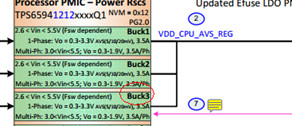
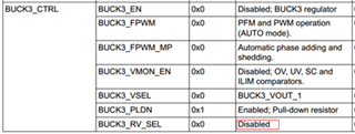
1. in PDN-0B, FB3 is used to monitor the VDDS_DDR. However, in SLVC32, the default NVM setting is to disable this feature(BUCK3_RV_SEL and BUCK3_VMON_EN). Which one is correct?

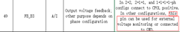
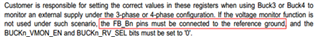
2. In the Checklist file, it is mentioned that unused FB pins can be connected to VCC or GND. however, according to TPS6594 datasheet, it must be tied to GND. Which one is correct?.

B&R

Lijia

  • Hello,

        There are two components.  The static settings which are copied from the NVM to the user registers during boot and then the sequences which change the user registers based upon a trigger.  Please note that all regulators and monitors are off in the static settings and these are turned on in a specific order as described in the power sequences.  https://www.ti.com/lit/ug/slvuc32/slvuc32.pdf#page=42

        Thank you for the feedback.  We will work to make the checklist more clear.  If unused then it should be connected to ground.  The datasheet will always be the definitive specification.

    Thanks and Regards,
    Chris

  • Hi Chris,

    Do we have any summary of register value of every state?

    B&R

    Lijia

  • Hello,

        We do not.  In most cases the rails are are enabled/disabled or the IO is changed from high or low.  This is not the case in the ACTIVE_TO_WARM and MCU_TO_WARM where the voltages are restored to the static NVM value.  Please let me know if this is not clear.

    Regards,
    Chris

  • Hi Chris, 

    I can understand what you say. I mean the register value, not the NVM value. Sorry if confused you. For example, after power on, all power rail is disabled. After that, a valid on request is reached to PMIC and BUCK 1 power rail is enable, state machine move to ACTIVE state, we must get 0x1 for BUCK1_EN bit. Do we have the summary for the register in every states?

    thanks!

    Lijia

  • Hello Lijia,

        We do not have a summary for the registers in every state.  Please remember the values stored in the NVM are written into the user registers after power up and the PFSM sequences also write to the user registers when triggered.  

        After Power On and before ENABLE pin on PMICA goes high:  

    • FIRST_STARTUP_DONE=1
    • Disable all residual voltage checking: BUCK1_RV_SEL=0, BUCKx_RV_SEL=LDOx_RV_SEL=0

      ENABLE pin goes high on PMICA (valid on request)

    Regards,

    Chris