This thread has been locked.

If you have a related question, please click the "Ask a related question" button in the top right corner. The newly created question will be automatically linked to this question.

TPS51220A: TPS51220A output current calculation

Part Number: TPS51220A


Dear Expert,

Good day!

I have 2 questions about the TPS51220A here ,

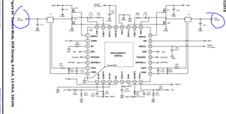
1 . from the datasheet reference design, it said the Vo1 and Vo2 support max output current is 8A , But form the calculation on the datasheet ,the Iocl(peak)=VOCL * 1/ Rs *( Rx + Rc)/ Rc

base on the parameter on the schematic , Vocl = 60mV ,Rs = 10.5 mR ,Rx = 7.5k ,Rc = 4.3K, So I peak= 15.68A    ,even though IOCL(PEAK) should be approximately 1.5 × IOUT(MAX) to 1.7 × IOUT(MAX). the result is Iout (max)  is  15.68/1.5(1.7) = 9.2-10.45A ,   it is not same to the datasheet descriptions , could you tell me is there any mistake I had made ?


2.What is the difference between non-droop in Current Mode and standard Current Mode?

BR,

Leon.liu

  • Hi Leon,

    I'll look into it and give you feedback tomorrow.

    Thanks,

    Andrew

  • Hi Leon,

    1. I think your calculation is correct. But as you can see in the equation, the Iocl(peak) will be lower with larger inductor DCR Rs. 10.5mohm is the typical DCR of the selecting inductor and its max DCR is 11.5mohm from its datasheet. The inductor DCR will also increase with increasing temperature and given DCR value in inductor datasheet is normally the value with room temp, so the Iocl(peak) will decrease more with higher temperature.

    Another point is that Iocl (peak) is the inductor peak current which equals to the Iocl (dc) + 1/2 inductor pk-pk current ripple. So normally, we will evaluate the relation between Iocl (dc) and Ioutmax.

    For OC limit setting, what we want is to first avoid the device triggering OC protection incorrectly during the normal operation. So we need to consider the worst case with low OC limit and keep that limit larger than the Iout(max). Some margin is also needed based on that. To avoid device damage, what we normally recommend is to make the inductor saturation current rating/power mos max current rating larger than the largest OC limit considering parameters variation.

    2. I think you can just refer to curves on datasheet page 14. With droop, the output voltage will reduce with increasing output current, as shown in the figure 25 and 26. With non-droop control, the output voltage keeps almost same with increasing output current.

    Thanks,

    Andrew