This thread has been locked.

If you have a related question, please click the "Ask a related question" button in the top right corner. The newly created question will be automatically linked to this question.

TPS22810: TPS22810DRV thermal shutdown

Part Number: TPS22810

About thermal shutdown of TPS22810
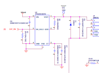
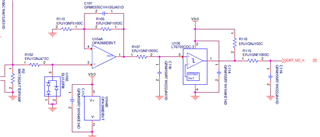
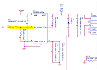
The circuit diagram is shown below.
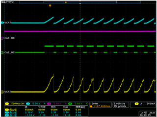
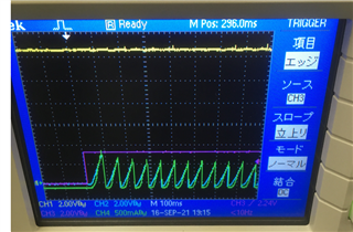
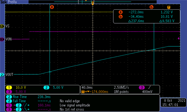
It also shows the observed waveform.
The voltage drops at startup. Is this because the thermal shutdown function of TPS22810 is working?

I don't understand why the voltage is off.

CH1:Current flowing through the IC

CH2:Vboost

CH3 and CH4 are my original monitoring circuit, so it might be ignored.

  • Hello,

    Thanks for reaching out on E2E!

    The TPS22810 will shutdown thermally when the junction temperature hits 160C typ. The switch then re-enables once the temperature drops below the Tsd-Tsd,hys value (130C typ). 

    However, thermal shutdown does not bring the input voltage low, in your case, Vboost low. It appears there is something going on with the system's input voltage that could explain the drop in current. 

    Possibly VCAT seems to be turning on and off with the "CAT_UC" signal? Are the two signals connected somehow? 

    Also, could you elaborate on why you chose to put a diode on the output? 

    Best Regards, 

    Elizabeth

  • Hi Elizabeth,

    Thank you for answering my question.
    I am sorry my explanation was not good.
    I would like to know if thermal shutdown function of IC cut off the output CH2 that is measuring at TP2 or not.

    "CAT_UC" signal is detecting under-current status after thermal shutdown cut off the output.

    My question is that even though the voltage(3.3V) and the current(950mA) are not too high, is thermal shutdown working?

    When the circuit is working normally, the voltage is 12V and the peak current is about 1.5A.

    Since I connect the DC motor, I put the diode on the output.
    The purpose of the diode is to provide a safe path for the inductive kickback of the motor.

  • To calculate your junction temperature, I'll need to know: 

    • Your ambient temperature 
    • Output current over time (is this VCAT, channel 1 in yellow?)
    • Output voltage over time (is this VCAT, channel 2 in blue?)
    • Also Input voltage over time for debugging purposes
    • Please elaborate regarding CAT_UC; Where is CAT_UC probing? 

    Are you operating in a hot environment? 

    Best Regards, 

    Elizabeth

    • Your ambient temperature -> Room temperature (Around 27 or 28 degrees)
    • Output current over time (is this VCAT, channel 1 in yellow?) -> Yes, Yellow is the output current measured by current probe.
    • Output voltage over time (is this VCAT, channel 2 in blue?) -> Yes, Blue is the output voltage at TP2.
    • Also Input voltage over time for debugging purposes -> Sorry, I cannot understand what you mean.
    • Please elaborate regarding CAT_UC; Where is CAT_UC probing? -> I put on a part of the schematics to explain CAT_UC.

    The current through the motor flow into the R2.
    The op-amp amplify the voltage that R2 * motor current.
    The comparator can detect the under current.

    CPLD detect the under current status over 40msec.
    So, I do not think TPS22810 is disable by CPLD.

    I would like to know if thermal shutdown function of IC is working or not.

  • Hello, 

    It is unlikely the device is entering thermal shutdown with only 0.95A and 3.3V over around 80ms starting at room temperature. 

    I find it peculiar that the output current seems to mimic the CAT_UC waveform as if it is enabling the output. 

    Could you probe the enable voltage on the EN_UVLO pin when this issue is occurring?

    This way we can see what signal is enabling the output of the device.

    Best Regards, 

    Elizabeth 

  • Hi Elizabeth,

    Thank you for your reply.

    I probed the EN_UVLO, but it is not disable.

    CH1:Vboost(Vin:Yellow)

    CH2:TP2(Vout_Blue)

    CH3:CAT_ON(EN_UVLO_Magenta)

    CH4:CN4_1pin(Motor_Current_Green)

    Regards,

    Yoshi

  • Hi Yoshi, 

    I will attempt to replicate this in lab using one of our EVMs.

    Can you confirm your test setup? 

    • Vin = 12V?
    • ON = 3.3V?
    • CT cap = ?
    • Cin = ?
    • Cout = ?
    • External QOD resistor = ?

    Best Regards, 

    Elizabeth

  • Hi Elizabeth

    I am sorry for the delay in reply to you.

    • Vin = 12V
    • ON = 3.3V
    • CT cap = 1.uF(C12)+4700pF(C7)
    • Cin = 220uF+0.1uF(C9) -> DC/DC converter output capacitor is 220uF.
    • Cout = 0.1uF(C2)
    • External QOD resistor = 0ohm(R5)

    I look forward to hearing from you.

    Regards,

    Yoshi

  • Hi Yoshi, 

    Thank you for that information

    I will get back to you by next week with my test results. 

    Best Regards, 

    Elizabeth

  • Hi Yoshi, 

    Apologies on the accidental 'Thinks resolved' click; I was trying to reply.

    I tested your condition in lab today and did not see the error you're experiencing.

    I doubt the device is thermally shutting off due to the low power dissipation and low ambient temperature. 

    Is there a chance your source is pulsing?

    Also, are you intending to have a rise time around 240ms? With a CT cap of 1uF, we would expect around a 240ms rise time.

    If you'd prefer, I can set up a call for us to chat about the issue when you're available.

    Best Regards, 

    Elizabeth 

  • Hello Yoshi,

    Also what are your DC output conditions such as Output resistance and total output including load capacitance? 

    Best Regards, 

    Elizabeth  

  • Hi Yoshi,

    Since this thread has gone on two weeks without a reply, I am closing/locking it. If there is another update here, please make a new thread.

    Best Regards, 

    Elizabeth