This thread has been locked.

If you have a related question, please click the "Ask a related question" button in the top right corner. The newly created question will be automatically linked to this question.

TPS61040: Large ripple and poor regulation

Part Number: TPS61040

I have a small PCB designed and assembled to evaluate the TPS61040 for a client. The input is from a Lithium Titanate battery (2.4V) and the output is set to 3.3 Volts to power the MCU.

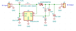
Please ignore the input/output voltages on the above clip of the schematic, the specification changed since the drawing was done.

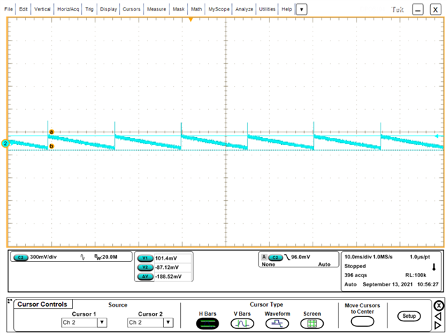
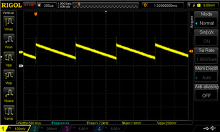
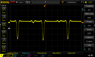
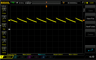
For testing the battery is replaced by a bench PSU, set to 2.4 volts. With no load connected I an seeing the correct voltage (3.3 volts) however, on my scope I see a sawtooth wave for of around 30Hz and 600mV peak to peak.

Also, I have noted that with a load of 100mA the output voltage falls well below 3.3 Volts.

Any help you can provide would be much appreciated.

Sid

  • Hi Sid,

    The device will enter PFM mode when the load is very small such as open load. While in PFM mode, the converter only operates when the output voltage is below the nominal output voltage. When this happens, the converter begins switching until the output voltage is regulated to the typical value. It can increase light load efficiency and cause a larger low-frequency ripple.

    Below is the ripple tested on EVM which is about 188mV peak to peak. the ripple is also depend on layout and measurement, bad layout and measurement will cause larger ripple.

    Performing Accurate Power Save Mode Efficiency Measurements

    Best Regards,

    Eric Yue

  • Thank you Eric, I have an eval board on order to enable comparison of the results to my PCB.

    I understand the PFM mode (light load) as you described it. However, I noted the large loss of regulation under a 100mA load. I do not have the PCB on the bench right now, however I remember the "nominal" voltage measured with a DMM dropping from 3.3V to around 3.0V. This seems excessive.

    Sid

  • Hi Sid,

    Is the consumption only large at 100mA load or continuously large when above 100mA load? Please provide the efficiency change when increasing the load. The current limit of TPS61040 is 350mA which is refer to inductor peak current, maybe 100mA load can trigger the current limit because of inductor ripple. Please also provide the waveforms of Vout, SW and inductor current to further confirm.

    Best Regards,

    Eric Yue

  • Hi Eric,

    excuse the delay getting back to you, I just received my evaluation board for the TPS61040 and got it on the bench. This board is giving very strange results. It is the -001 board that produces 18V output from, say, a 3.3V input. With no load it produces the correct output voltage and the ripple is 200mV peak-to-peak. When I apply even small load (10mA) the output periodically dips to about 10V. This is awful regulation.

    No load:

    The ripple above is 200mV peak-to-peak.

    10mA Load:

    As you can see, the dip in the output voltage is almost 7V.

    This is the EVB right out of the box.

  • Hi Sid,

    The ripple with no load is normal because the chip works in PFM mode now. For 10mA load, the sudden voltage dip is strange and the frequency is very low. Please attach the waveform of Vin, Vout, SW voltage and inductor current to further analyze. And how is this10mA load be loaded?

    Best Regards,

    Eric Yue

  • Thank you Eric.

    Since this is all with the TI eval board I have decided to abandon using this part.

    Again, thank you for your efforts.

  • Hi Sid,

    Sorry for the unexpected test results. Through our bench test, the EVM operates normally at 3.3V to 18V (10mA). The chip also works well in many customer applications. I believe this is due to test setup or other incidental events and we can fix it through debugging like I replied before. Blush

    Please feel free to reply any update about this issue.

    Best Regards,

    Eric Yue