This thread has been locked.

If you have a related question, please click the "Ask a related question" button in the top right corner. The newly created question will be automatically linked to this question.

Please provide the key parameters of the transformer suitable for this power circuit

Other Parts Discussed in Thread: LM73606, LMR36520

Dear sir,
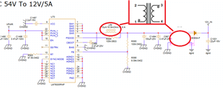
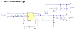
Our power circuit is as follows: (Accessories are key parts specifications)
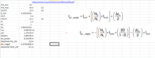
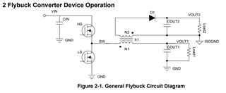
It is TI's 54V to 12V power supply circuit. Then output 12V current (about 50W) through the transformer
Do you suggest that I take key parameters such as the transformer turns ratio and induction value in the power supply circuit as an important reference for selection or customization?
thanks for your help!
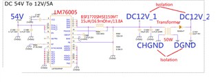
5732.LM76005RNP.pdf4621.BSF1770SMSE150MT承認書.pdf

  • Hi,

    I would start with this app note on how to design a isolated flybuck converter. The topics discussed in this app note will help with picking the appropriate coupled inductor which it sounds like you are interested in knowing here.

    Please see referenced app note : https://www.ti.com/lit/an/snva790/snva790.pdf

    Regards,

    Jimmy

  • Dear Sir

    I am a Baseband electronic engineer. The design field of Transformer is not my specialty. The 54V directly to 12V power supply posted in the message before is the circuit used in my current product. Originally, there was no Transformer, but the power IC directly outputs DC12V. For system use, however, isolation between the 12V output by the power IC and the 12V required by the system is the correct design, so Transformer must be used. And the Transformer manufacturer must help to customize the Transformer, and the key parameters of the Transformer must be provided before ordering. They can make it based on
    The design of Transformer is not my specialty. It is not easy for me to understand the design information you provide to analyze the key parameters of Transformer. I have also asked the FAE of the agent but they don’t seem to understand it and suggest that I go directly to E2E and consult TI. AE
    Because of the time pressure of product development, can you please help me analyze the current 54V to 12V power supply circuit. If I want to use a Transformer that can convert 12V (50W), the coil turns ratio, inductance value, etc. The key parameters, I will provide these to the Transformer manufacturer to customize the Transformer
    Thank you for your assistance!

  • Hi,

    I just quickly made a calculator to doublecheck the design. See below:

    I went through the app note to confirm if the LM73606 is a good fit for this flybuck application, and confirmed that it should be okay to use.

    The calculation calls for a minimum of 11uH so 15uH should be plenty of inductance here.

    In this case you would replace the existing 15uH single inductor with a coupled inductor and a turns ratio of 1:1. 

    Regards,

    Jimmy

  • Dear Sir
    1. Is your suggested 1:1 coupled inductor similar to the attached specifications?
    2. As shown in the figure below. I have a question that the original circuit uses 15 uH single inductance (2 Pin) after changing to 1:1 coupled inductance (4 Pin), can you tell me how to connect coupled inductance (4 Pin) on the circuit ) Can isolate the 12V and GND on both sides of the coupled inductor?

    VISH_S_A0004339953_1-2569504.pdf

  • Hi,

    Yes the inductor and transformer will be changed to just a single coupled inductor. 

    You can refer to the app note for more details but the below circuit diagram should illustrate the connection.

    Below is an actual use case condition using the LMR36520:

    Regards,

    Jimmy