This thread has been locked.

If you have a related question, please click the "Ask a related question" button in the top right corner. The newly created question will be automatically linked to this question.

TPS543C20: Monte Carlo Simulation Issues

Part Number: TPS543C20
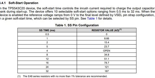
Other Parts Discussed in Thread: TPS54020

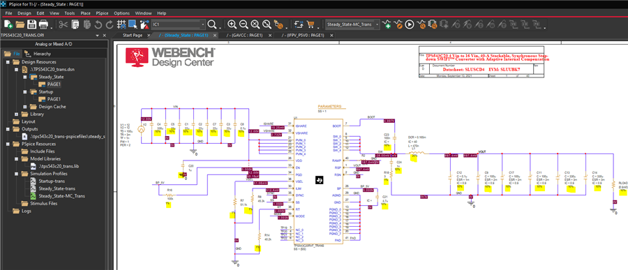
When I ran the TPS543C20 "steady_state" example model that downloaded from the TI site, PSPICE results ran OK by itself. However, if I added the tolerance at each component and ran the MC analysis, the outputs V(VOUT) varied all over the place. I ran this example because it is supposed to be the "golden circuit" and I tried to compare this to my other circuits which have the same issues.  The circuit is so sensitive that if any component values change slightly, the circuit will fail. Please advise. The following is the detailed problem explanation.

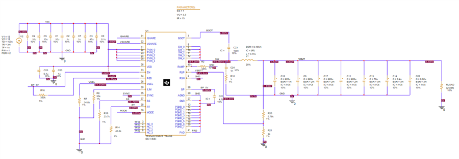
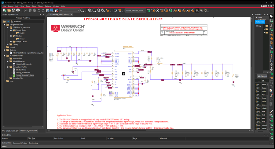
Monte Carlo Analysis with TPS543C20 Steady_State Example Model Issue

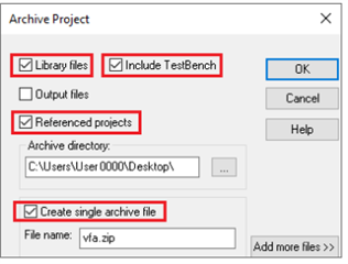
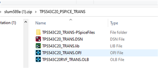
  • I downloaded the PSPICE model from TI site.
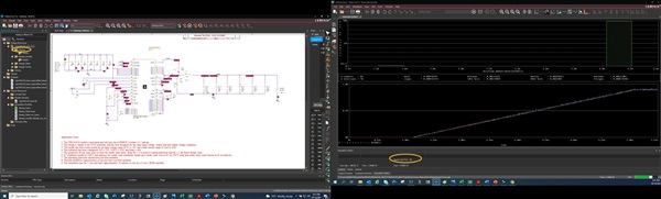
  • Open the PSPICE project and run the project file.

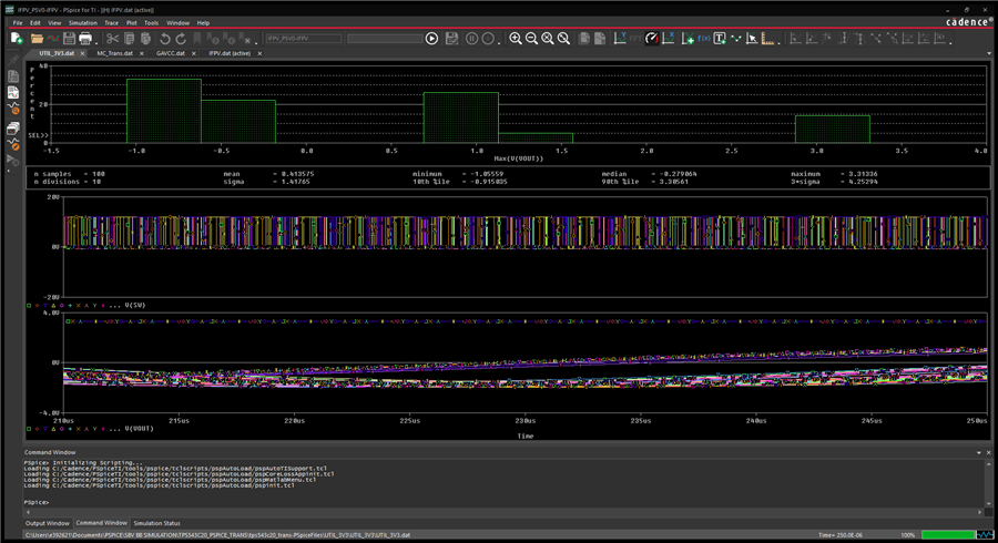
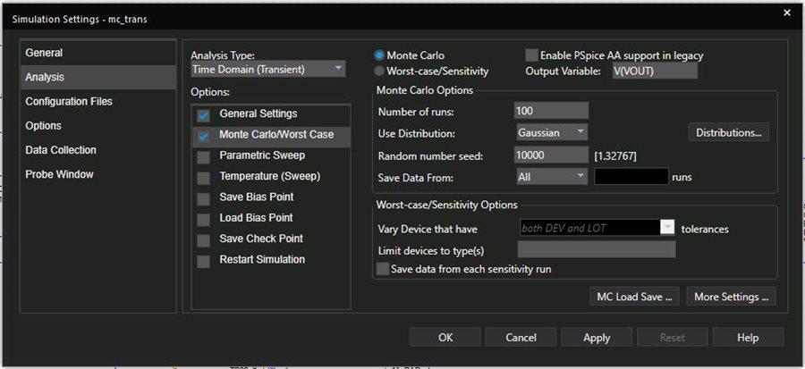
  • The “included” example Steady_State model runs OK by itself. I then added the tolerance at each component and start the Monte Carlo with 100 runs.

Problems:

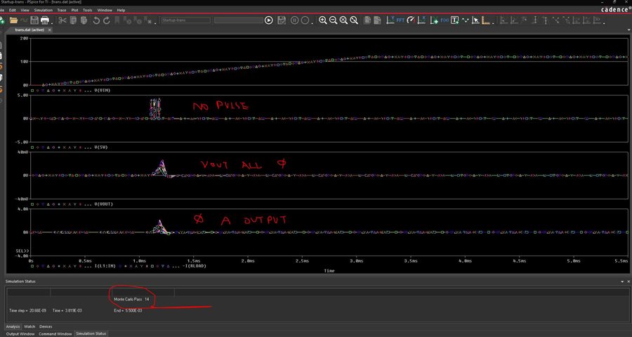
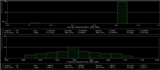
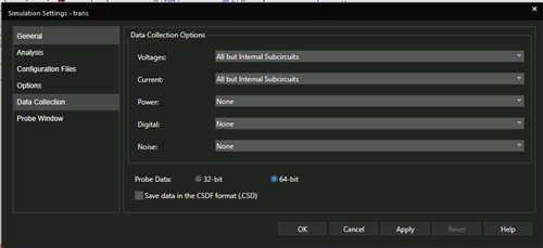
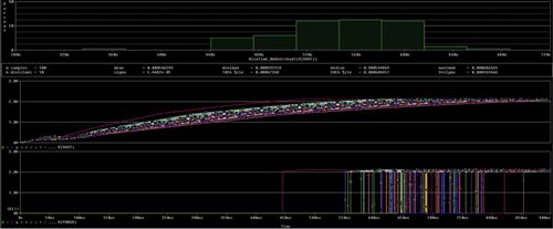
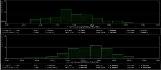
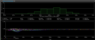
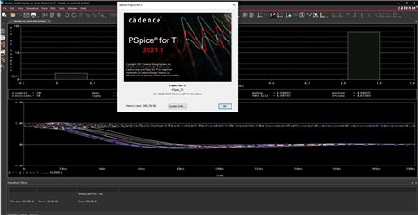
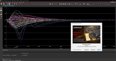
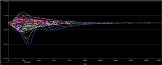
The V(VOUT) output value varies from 0 to 0.9V. The normal distribution of 0.9V is supposed to be the expected values.

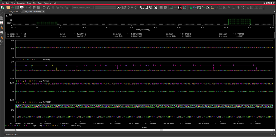
The I(RLOAD) varies from 0A to 40A.

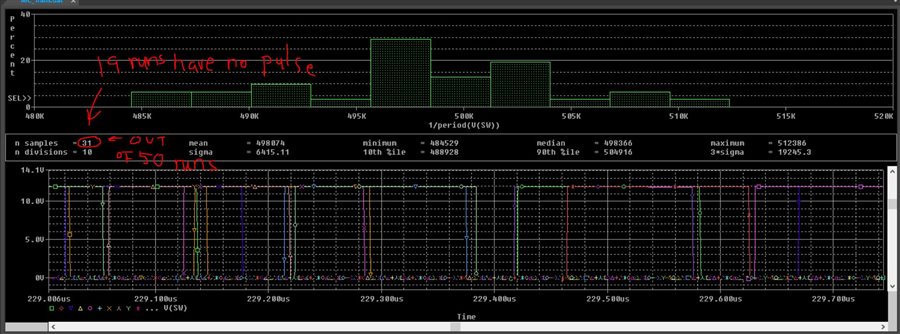
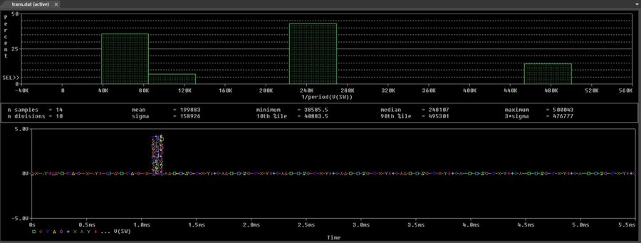
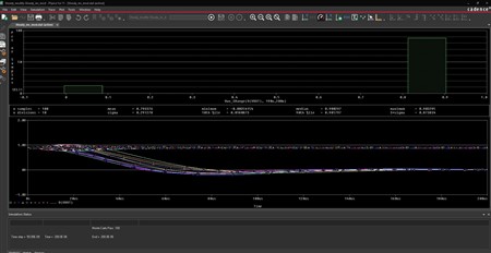
The V(SW) stops (0V) in most of the runs.


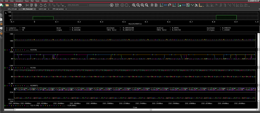
  • The reason I found this problem is because I ran a lot of my circuits and they have the same issues. If I vary any component values slightly, the output voltage will failed by going to zero and the switching pulses will stop.


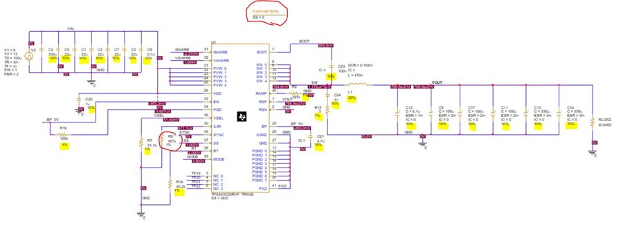
My other 12V to 3.3V 15A Circuit

  •  

    Sorry to hear you are having issue with the simulation.  One thing that I noticed in your simulation was the Rramp resistor is 187 +/- 10%.  I don't know if this is the root cause of the issue you are seeing, but Rramp digitally selects discrete compensation scalers for the internal compensation ramp, if the tolerance on Rramp is sufficient to select alternate ramp values, the circuit may not be tolerant of the discrete compensation selection, which could be contributing to the issue you're seeing.

    Can you try reducing the tolerance on this resistor to 1% and see if that addresses the simulation issue you are seeing?

  • Peter, 

    Thanks for your reply.

    I updated the 187K RAMP resistor tolerance to 1% at the example circuit and run the MC for 50 times. 

    The results are almost the same as the previous. The distribution of pass and fail are the consistent with about 60% and 40%. 

  • Hi Alan,

    Our US team are looking this and will reply you soon.

  • Alan,

    Thank you.

    I am asking our simulation team to work on it to identify what the issue is.

    A couple of questions:

    1) What are the Monty Carlo settings you are using?  I'm wondering if the MC runs are varying the internal components from the model, and if they are, what tolerance they are using.

    2) On the runs that are failing, is the output voltage coming up, then stopping?  If so, what voltage is it coming up to?  What is the rise time on VOUT?

      The Variable SS = 1, sets the converter for "fast start-up", I'm wondering if the fast start-up is too fast for some of the Monty Carlo runs and some of them are triggering protection features such as OV, UV, or ILIM with the output capacitor tolerances.

    You could try setting SS = 0 and using the soft-start time, or you could try increasing the current limit by changing the ILIM resistor to 60k.

    3) Can you compare the switching frequency of several runs?  Is the switching frequency the same or different?

  • Peter,

    Thanks for you help.

    1) The following is the MC setting that I am using for 100 runs.

    2) For the runs that are failing, the V(VOUT) are always zero at steady state.

    For the startup state, setting the SS=0 and ILIM resistor to 60K ohm using the TI example startup circuit (download from TI site), I added the tolerance at each component and run the MC for 14 runs. The run time (>20 mins each) is 10 times slower when SS is 0. The switching pulse tried to start at 1ms and then stop (100% failed). This is worse than SS =1 which there were 60% pass with output.

    3) When SS=1 with the steady state model (looking at 200us range) in 50 runs, the 31 out of 50 runs have switching pulse. Frequency is around 500K Hz.

    When SS=0 with the startup model (looking <5us range) in 14 runs, the frequency of 14 runs are all over the place. They last only 0.1ms.

  • Hi Alan,

    Peter & simulation team are working on this, will reply you soon.

  • Hi Alan,

    I have picked this up. Could you please share the model files so that we can have a look at it. I have added below the steps to archive the project.

    1. Go to File → Archive Project
    2. Check the following checkboxes:
      1. Library Files
      2. Include TestBench
      3. Referenced projects
      4. Create Single Archive File
  • Alan,

    Thank you.  Karthik and his team are looking into this.

  • Hi Alan,

    I wanted to inform you on the progress of this. The root cause for why the steady state testbench was failing is it was hitting current limit.

    The reason for this being steady state testbench is generally provided to save time by trying to give some key node voltages and initial condition to calculate bias point close to steady state and reach steady state faster. The downside to this in initial few cycles, the voltages can be unstable due to bias point calculation. This is causing the steady state to fail. The easiest fix to this would be to increase the ILIM resistor so that it doesn't trip current limit(since we're not interested in current limit right now). On doing this, I am able to get 49/50 runs to be switching. I have added the snapshot of result below for your reference. The upper result is average output voltage and the lower result is frequency.

    I am currently trying to figure out why the one run is failing and will get back to you tomorrow.

  • Karthik,

    Thanks for the reply.

    For the current limit, we had tried this ILIM approach in the previous post per Peter's suggestions. We had changed the ILIM resistor to 60k and also tried the "transient" and "startup" scenarios (with SS=0/1) and both failed (See previous post). Transient yielded 31/50 runs and startup model yielded 14/50 runs.

    For the ILIM resistor calculations, the ILIM 60K resistor should allows up to 70A per TPS543C20 datasheet page 21 (See my below calculations).  That 60k ohm of 70A should be sufficient for this 40A application. What ILIM resistor vales would you use? What current limit is being set? Please advise.

    My calculation on Mathcad:

    I tried the transient run with higher ILIM resistor >60K with no success. How did you yield 49/50? Same issue applied to the "startup" model.

  • Hi Alan,

    It looks like I deleted some of the posts by mistake. Apologies for that!

    1. To clarify, steady state is an additional feature that is meant only for reducing simulation time. It helps the user to get to steady state quickly to check parameters like output ripple,Fsw and for transients. It should not be taken as an reflection of the actual device(for the first few cycles atleast, in this case upto 150us). When the device operates in startup, we're not going to hit 60A limit for the 40A load.

    2. The current limit calculations that are mentioned before are for low side MOSFET. Also, one miss that I see in the calculations is the RDS. RDS for low side MOSFET is 0.9mΩ. So the low side OCP comes out at ~46A. In addition, there is a high side short circuit limit of 60A, which is tripping in these cases.

    3. Regarding simulations failing due to large size, please correct the simulation data capture as mentioned below.

    Go to PSPICE --> Edit Simulation settings --> Data collection --> Choose 'All but internal subcircuits' from the drop down.

    This should help with low data file size and allow you to run more conditions.

    Also, I am sorry that I gave you the impression that I'm trying to get maximum yield. I saw most of the resistors have 1% tolerance, so I modified the load resistor. Also, if the goal is to see how the model performs for load regulation, I can disable the current limit in the model so that it doesn’t trip. As I have mentioned above, the trip is only happening due to initial DC bias point miscalculation and it will not occur if we run startup, but since we cannot run startup due to run time constraints. We can use this approach. Let me know your thoughts on this.

  • Karthik,

    Thanks for your reply. I think we have forwarded our response through Javier that we have decided to try the modified model without the current limit. 

    I think we can use your transient model to evaluate the load regulations and the startup model to study the soft-start timings with MC. Please let us know if you have a better approach.

    As you mentioned in your previous post, the startup model will not have the current tripping problem due to the DC bias point miscalculation. I had ran the startup simulation for 2 days. The results are too good to be true. I don't see any failures or tripping but I see no variations in the V(VOUT) rise times and settling voltages. Please verify that on our model.

    Regarding the simulation failing due to large file size, I had also tried your recommendation of setting the "All but internal circuit" but it still crashed t 86th run (see the sim results above yellow circle).

    The followings are the data collection settings. Please let us know if it is set correctly.

    Please forward us the modified model if it is ready.

    Thanks,

    Alan 

  • Hi Alan

         How did you vary the soft start time? What parameters are varied for the start up simulation? 

    The SS pin in the device sets the SS time using discrete value of resistors. So variations in the resistor should not affect the soft start time as long as they are within the detection thresholds.

    In the model, if you set the SS parameter=0, the startup time will be 0.5ms, If you set SS=1, it will be 4ms and so on 

    In the simulation profile, there is also an option to save the markers (probes only) - this will save the data file size even further.

    But looking at the fact that simulation fails always at the 86th run, makes me think that it might be something else.

    Regards,

    Gerold

  • Gerold,

    All the parameters varied were shown in the first picture of my previous post (left: circuit, right: output).

    I would think even the SS is set to 0.5ms or 4ms, etc, the output will still be varied because output caps and inductors will vary the output startup time by different charging and switching time of output C and L. See the following example of TPS54020's Vout and power_goood (I don't see that in this variation in  TPS543C20).

    Our startup circuit SS is set to 0 but the simulated SS time is 4ms. Is it supposed to be 0.5ms per your previous post?  How can we verify that against the datasheet? What resistor is used in the startup model? How could we prove our design?

    Thanks,

    Alan 

  • Hi Alan,

    1. Please find the updated model below. I simulated the model across 100 corners and the model works fine for all. I have also added results below for reference.

    TPS543C20_17OCT.zip


    2. I couldn't run the Startup on my system as it takes a lot of time. However, I believe the results you are getting should be expected. My reasoning is, as long as the current demanded by Load (resistor, output cap) is being met, I would expect that the output voltage would rise at a constant rate as defined by soft start.

    I am assuming that you're getting different soft start times in TPS54020 because of one of the two reasons. One, it implements a capacitor based soft start charging time. So, if you vary the capacitor using MC, it varies the soft start time. Two, it could be due to cycle-cycle current limiting.

    Also, as Gerold has mentioned in previous posts, the TPS543C20 device uses Discrete resistor based soft start time, so the soft start should not vary.

    3. I believe Startup testbench is causing issues due to large data size. Please check if the disk space is sufficient and if you can clear some. The data collection settings shared by you are correct. You can further reduce the data size by using "At markers" options for both Voltage and currents in data collection, but you would have to manually add voltage, current probes to the nodes you want saved.

    4. The device implements resistor based soft start selection by connecting a resistor from SS pin to GND. Since the SS pin is left open in Startup testbench, it corresponds to 4ms of soft start time. 

    Please let me know if you have any other questions.

    Regards,

    Karthik

  • Karthik,

    I ran your attached "Steady_modify" model but the simulation only yielded 90/100 runs. 

    Please advise.

    Thanks,

    Alan W

  • Hi Alan

    Karthik is looking into this and will feedback to you soon.

    BR

    Ruby

  • Hi Alan,

    It worked fine for me when I ran it again. I have again re-attached the model for your reference. Please check.

    Also, other thing you can probably check is the simulator version that you are using. This shouldn't affect according to me, but we can confirm.

    I am using 17.4-2019 S020 patch. 

    TPS543C20_28OCT.zip

    I have added below the model results.

    Regards,

    Karthik

  • Karthik,

    Thanks for the reply. 

    I have been using Cadence "PSPICE for TI" 17.4-2020 S007. I ran your 17OCT and I got the previous results.

    If I ran your 28OCT with Allegro 17.4-2019 S009, I would get the followings which is more identical to your results.

    Is there a bug in the "PSPICE for TI"? That TI software seems to be more updated (-2020). Is the Allegro version the correct results? I like PSPICE for TI because it has all the TI products in the library. Should I stop using that? Are all the results that I have been running with PSPICE for TI not valid?

    Different version of software produced "drastically" different results that makes me concerned. The key is that we need to go with the one which is more representative to the actual circuit performance.

    Thanks,

    Alan

  • Hi Alan

    Karthik is looking into this and will feedback to you soon. Thanks.

    BR

    Ruby

  • Hi Alan

        The underlying simulation engine for Pspice for TI and Allegro are the same. So, I am surprised by the differences unless there is something different between the 17OCT and 28OCT model. That being said, if Allegro gets you going, please use that. In the mean time, we will reach out to Cadence to see why we get these differences.

    Regards,

    Gerold

  • Hi Alan, Gerold,

    I checked on this. The reason for mismatch is PSPICE for TI is replacing the updated lib file with the installed library(original model). There is no bug with PSPICE for TI. We can replace the library file later and work with PSPICE for TI. I have added the result below:

    However, since PSPICE for TI has a maximum limit of 3 traces for non-installed libraries., it would be better to use Allegro in this case.

    Regards,

    Karthik

  • This thread is still listed as unresolved.

    Is this resolved, or are we still working on it?

  • Alan,

    Has your issue been resolved?