This thread has been locked.

If you have a related question, please click the "Ask a related question" button in the top right corner. The newly created question will be automatically linked to this question.

TPS92518HV: LED Driver for 10A / 24V application

Part Number: TPS92518HV
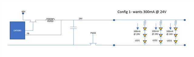
Other Parts Discussed in Thread: TPS92518, LM5085

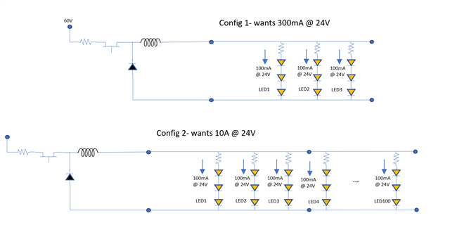
Hello- I am looking for candidate devices for LED drivers for diving light strips.  The number of strips can be variable adding more 24V strings of LEDs in parallel up to a 10A total current draw.

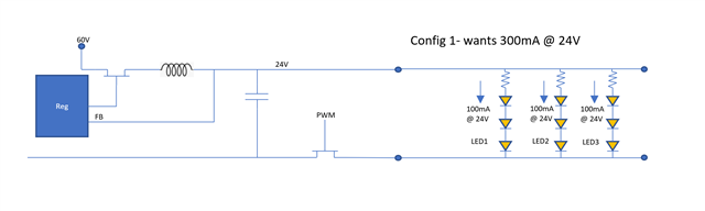
PWM dimming at a visually undetectable frequency is required.

Input voltage is up to 60V

Is the TPS92518HV a good candidate to use?

Can the device be set so that if there is one set of LEDs that only needs, say 100mA, the voltage is still at 24V.  Same if there are 1000 sets requiring a collective 10A?

Can the two outputs of this device be combined in parallel to achieve the 10A requirement?

Thanks!

  • Hello Ryan,

    The TPS92518 is a good candidate for this.  The part regulates current so when you say the LEDs need only 100 mA the TPS92518 will deliver 100 mA and the voltage will be whatever the LED stack voltage is at 100 mA, it cannot control voltage since it is a current source to drive LEDs.

    Are you planning on setting the average current via PWM input?

    Are you looking at one design with multiple output current settings?

    Channels can be paralleled however it could also be designed to output 10A from one channel since it is a controller.

    Note sure I understand this:  "Can the device be set so that if there is one set of LEDs that only needs, say 100mA, the voltage is still at 24V.  Same if there are 1000 sets requiring a collective 10A?".  Are you saying 1000 strings running 10 mA running from one device?

    Best Regards,

  • Hi Irwin- thanks for the response!  Please forgive my dumb questions- I'm new to current mode controllers.

    My understanding is you set the current mode controller for a specific current, say 10A in my case, and the controller will attempt to provide that current.  If your load is fixed, that works great.  The problem is I don't know what my load could be.  If only one string of LEDs is connected, the rated current for the LEDs is, say 100mA per set, for 300mA total at 24V.  Since this is so far below the max 10A setting, I am guessing the controller will be outputting close to 60V across the LED strings, driving their current up to maybe 250mA per segment for an actual current of 750mA and likely overdriving the  LEDs and limit resistor.  Whereas with a full load of 100 LEDs, we would be reaching the 10A limit, and the voltage would be around 24V on the lines and the LEDs would be operating at their designed current levels and everything is good.

    It seems that a voltage mode controller is more what I want for this situation, but then dimming becomes difficult (maybe there is a good way to dim this configuration?  Note that I need digital dimming with maybe 10 preset levels)

    Here's a diagram showing an example min load case vs. a max load case

  • Hi Ryan,

    So if you set the controller to 10A it will damage the LEDs/limit resistors if you only connect three strings.  What are the resistor values in series with the LEDs?

    Does the system know how many LED strings are attached or is this something the end user decides?

    If I take 100 mA at 24V and 250 mA at 60V the series resistor calculates to 240 ohms.  This would be 100 mA without the LEDs present at 24V, 24V/240 ohms.

    It would be helpful to know what the LEDs/resistors are to help figure this out.  The datasheet and number of series LEDs would be helpful as well.  I'm guessing what you want is a voltage output and some way to limit the current to each LED string.  using a resistor is difficult if you don't want to be inefficient.  This is due to the Vf of the led dropping with temperature.  If you try to regulate current for each string that would require multiple connections at the output of the supply and a lot of additional circuitry.

    Best Regards,

  • I don't have details on the exact LED strips to be used- I'm trying to accommodate a generic strip.  The 100mA example was a number chosen by me for easy calculations :)   Examples of the LED strips:  2835 120 STRIP LIGHT SERIES (risingsunled.com),  Lumilum_IP20_24V_Single_Color_and_RGB_Strip_Lights_1.pdf (shopify.com)

    My goal is to be able to power and dim up to 10A / 240W worth of strips from this one output.

    Would an intermediate power stage dropping the 60V to ~28V going into the TPS92518 be a feasible solution?

    Thanks,

    Ryan

  • Alternatively, could I use a 10A DC/DC regulator and put a PWM FET between it and the LED strips like shown here:

    Will DC/DC converters handle the load switching well?

  • Hi Ryan,

    Those leds want a voltage source which also makes this easier to design what you are working on.  "Would an intermediate power stage dropping the 60V to ~28V going into the TPS92518 be a feasible solution?"  The TPS92518 is a current regulator.  If you set it to 10A it will run near maximum duty cycle so the output would be near 28V if the input is 28V.  You're better off just creating a 24V voltage output from the 60V.  These LEDs don't want that, they just want 24V.  You could run a string or multiple strings from a current regulator but it would be only one configuration.  Example would be three strings, the TPS92518 would need to be set to 300 mA output.  This would be the only configuration this would work with.

    That depends on the DC/DC converter and PWM frequency.  That can go from full load to no load and back.  It will also depend on how fast you want to be able to change the light output via the PWM duty cycle.

    If there is a lot of output capacitance and low band width it would work well but you couldn't change the PWM duty cycle very fast.  It can also work well if the bandwidth is high enough to respond to the load steps though there can/will be overshoot and undershoot if there is a control loop but it would allow quick PWM duty cycle change.

    I noticed one stated must be run with a Class 2 power source.  This is a safety spec which limits the power supply output power to below 100W.

    Best Regards,

  • OK, so for a voltage mode buck regulator, I see the LM5085 buck converter meets my basic specs for input/output voltage and current.   The datasheet mentions ultra-fast load transient response.  Can you tell me if this is an appropriate part or if I am missing any gotchas?  My goal is to run the PWM FET fast enough that flicker isn't evident when dimming the LEDs.  That might take some experimentation to determine what frequency is required.

    Thanks again!

    -Ryan

  • Hi Ryan,

    I don't know this part, the DC/DC voltage regulators will be supported by another group.  However reading the datasheet I have two concerns.  One, it's a P-channel controller.  P-channel MOSFET tend to have quite worse performance over N-channel MOSFETs.  It'll work however the MOSFET cost will be quite a bit higher than a comparable N-channel MOSFET.  Two, I'm not sure if this can run at very low output power due to how it works.  It appears to foldback frequency but it seems that it'll always be running which means minimum load requirement or running into OVP.  It may be best to search on DC/DC for your application or send out another post.

    PWM frequency is quite interesting.  Generally above 100-120 Hz it isn't directly noticeable but there are strange things that happen with motion and also sampled systems such as a digital recording.

    Best Regards,

  • Hi Irwin- Thank you for your help in understanding the 92518.  This conversation has educated me a lot :)