This thread has been locked.

If you have a related question, please click the "Ask a related question" button in the top right corner. The newly created question will be automatically linked to this question.

TPS62903: LED driver application

Part Number: TPS62903

Hi Team,

Our customer would like to use TPS62903 as LED driver like the one in Figure 8-80 of the datasheet. They have inquiries as follows;

- Our light product has flash mode, what is the min switch on/off frequency of EN pin?
- The voltage of FB pin can be easily set to lower values than nominal by using the SS/TR pin. What is the min voltage of FB pin? Can we set it to about 10mV?
- Please see the picture at page 10 of the datasheet. If we want to use a 200~400Hz PWM to control the brightness of LED, what should we do?

Regards,

Danilo

  • Hello, 

    the ratio between SS and FB is 0.75. this means the FB is set to 0.6V and SS can go as low as 0.8V. 

    please go thru this app note. it is the same concept for the the TPS62903.

    https://www.ti.com/lit/an/slva451a/slva451a.pdf?ts=1631720503281

    for the min EN time, I will come back to you on this. 

    thanks! 

    Tahar

  • Hello, 

    The typical required time for the EN to take effect is 0.6ms. (max of 1.8ms)

    with 200Hz to 400Hz (2.5ms to 5ms), that is plenty of time for the EN. 

    Please see figure 2 in the application note. 

    thanks 

    Tahar 

  • Hello Tahar,

    Thank you for the feedback.

    Please kindly give the reply to more questions below. Thank you.

    - our light product has six current modes. If the max effect of EN pin is about 1.8ms, looks we can not use 200Hz to 400Hz PWM to control the EN pin to adjust those six current modes. Do you have any solution to different current mode control? Possible to use the MODE/S-CONF pin for 200Hz to 400Hz PWM control?

    - If the output current of a single power LED is 3A, can the FB be set to 0.1V or lower? Then the efficiency can be keep at about 86%.

    Thanks and best regards,

    Steven

  • Hello Steven, 

    You can use equation 19 in the datasheet to set the VFB to lower values. 

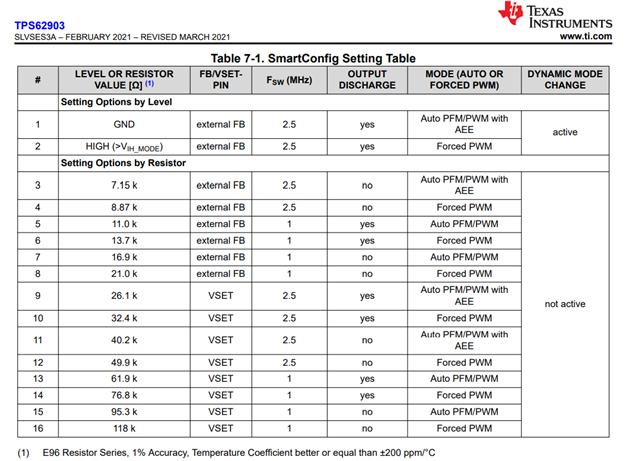
    MODE/SCONF pin can be used to set to select different modes (PFM and FPWM modes), two Fsw (1MHz and 2.5MHz), and also the Feedback (Internal vs. External). 

    Thanks! 

    Tahar

  • Hello Tahar,

    Thank you for the fast response.

    For the MODE/SCONF pin setting, I don't know how to process it. Please see the picture below. Could you please give the reply to following questions? Thank you.

    - In our 3A lighting product, when the voltage of FB pin sets to <=0.1V, should I select external FB mode or VSET mode?

    - If OUTPUT DISCHARGE is YES, will SW pin output the voltage?If OUTPUT DISCHARGE is NO, will SW pin keeps to output 0V?

    - At Forced PWM mode, is the duty cycle of PWM fixed? If not, how can I change the duty cycle?

     .

    Best regards,

    Steven

  • Hello Steven, 

    1- you can the external FB 

    2- The purpose of the discharge function is to ensure a defined down-ramp of the output voltage when the device is being disabled but also to keep the output voltage close to 0 V when the device is off. There is an internal bleeding resistor connected to VOS that get enabled when the device is off to ensure the VOUT ramps downs to 0V. The discharge function is enabled as soon as the device is disabled, in thermal shutdown, or in undervoltage lockout. once the device is disable the device will stop switching regardless of  discharge function.

    3- In FPWM, the switching frequency is well maintained however the Pulse width that changes as the load changes. for a fixed IOUT, the duty cycle changes with with VIN/VO ratio. 

    Thanks! 

    Tahar  

  • Hi Steven, 

    for question 3, you can use equation 3 in the datasheet to estimate the TON time  in FPWM and  continuous conduction mode (CCM)