Dear team
Could you help to review the schematic?
Many thanks
Denny
This thread has been locked.
If you have a related question, please click the "Ask a related question" button in the top right corner. The newly created question will be automatically linked to this question.
Hi Denny,
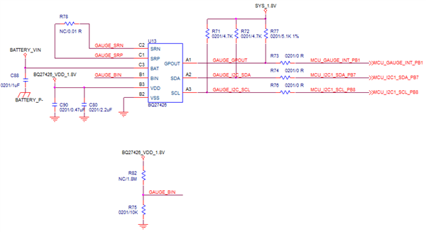
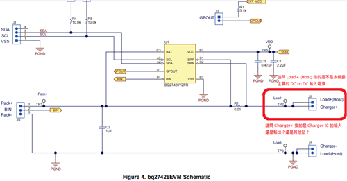
It looks like they are missing connectors for a load/charger. Also they need to Kelvin sense connect SRP to the positive battery terminal (PACKP) side of the external sense resistor and Kelvin sense connect SRN to the other side of the external sense resistor, the positive connection to the system (VSYS). Please have the customer refer to the schematics in the Datasheet and EVM User's Guide for these connections.
Best,
Jessica
Hi Jessica
Thank you your recommend.
1. The customer have modified the circuit. Is the schematic ok?
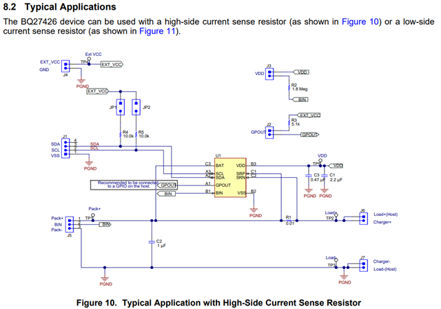
In the datasheet reference circuit :
Figure 10. Typical Application with High-Side Current Sense Resistor .
2. Figure 11. Typical Application with Low-Side Current Sense Resistor. In the EVM reference circuit diagram is High-Side. Is the High-Side more recommended
Will High-Side consume more power?
Many thanks
Denny
Hi Denny,
I don't see any changes to the schematic.
Both high side and low side sensing work for this gauge so both are recommended. The power consumption should be similar.
Best,
Jessica
Hi Jessica
Sorry, I update the mistake file.
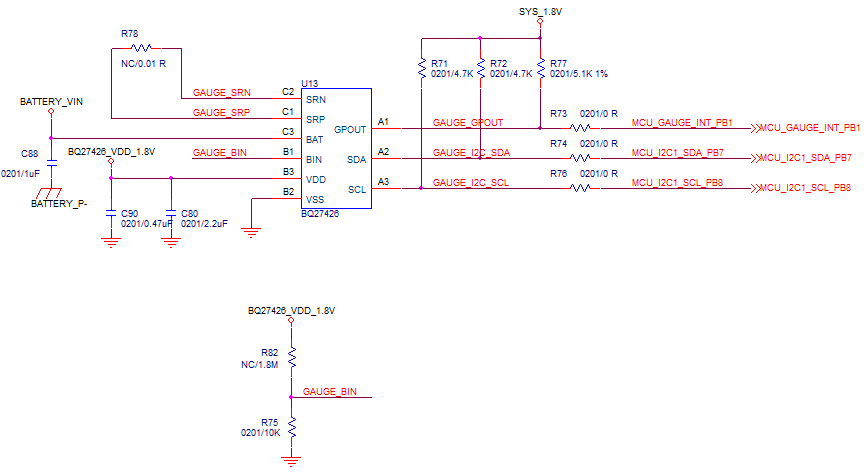
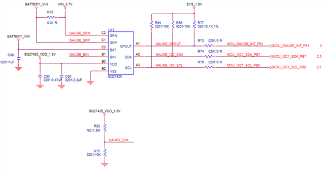
Please help to review the updated schematic as below. Update R78 to High-Side Current Sense Resistor And change SCL and SDA Pullup Resistors to 10K (originally 4.7K)
Many thanks
Denny
Hi Denny,
Where are they planning on connecting the load/charger? What else is VIN_3.7V connected to?
Best,
Jessica
Hi Jessica
Thanks your reply.
BATTERY_VIN is directly the output of the battery.
VIN_3.7V is the output of the charging IC,
It is also the input power supply of DC /DC.
Dose the schematic of BQ27426(U13) need to modify?
Many thanks
Denny
Hi Denny,
Thanks for sharing the whole schematic, it made it a lot easier to understand what they were doing in their original schematic. It looks good to me.
Best,
Jessica
Hi Jessica
Thanks your reply.
The customer have some confuse about the connection of J6 and J7. Could you help to recommend?
1. Is Loat+ Host meaning to connect to the input of DC-DC?
2. Is Charger+ meaning to connect to the input of charge ic?
Many thanks
Denny
Hi Denny,
1. Load+ means to connect it to the positive (high potential) part of the load (the part of the system the batteries are supplying power to).
2. Charger+ means to connect it to the positive terminal of the charger
Best,
Jessica