Because of the holidays, TI E2E™ design support forum responses will be delayed from Dec. 25 through Jan. 2. Thank you for your patience.

This thread has been locked.

If you have a related question, please click the "Ask a related question" button in the top right corner. The newly created question will be automatically linked to this question.

UCC3895: RMS currents calculation

Part Number: UCC3895
Other Parts Discussed in Thread: UCC28950, UCC2895

Hello TI.

I am a little bit confused by the way secondary RMS current is calculated in the datasheet. Let me explain what I mean:

According to this:

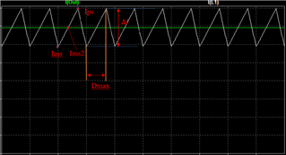
The picture of the secondary currents will look like:
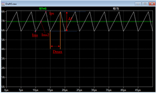
Where I(Out) is otput DC current (DC component of inductor current). And I(L1) is the inductor current (DCcomponent + AC)

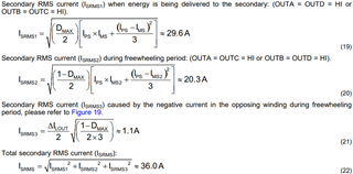
Then there is calculations of RMS currents:
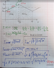
I thought that classical way to calculate RMS value of a DC+Ramp is the follow:

(Numbers are just for example, LTspice shows rms value of a 6.94A for the inductor current)

So can anybody explain what's going on in the datasheet? Why is there Dmax/2 and why instead of just Ims2^2 (DC^2) there is Ips*Ims? And why (Ips-Ims)^2 is not divided by 2? (Ips-Ims=delta I)

Regards,

Vasiliy

  • Hello,

    The calculations in the data sheet for RMS current on the secondary are for a voltage doubler.  This is the RMS current in each winding.  That is why Dmax is divided by 2.

    The one in the UCC2895 data sheet seems to have been updated with the equations from the attached applications note written for the UCC28950.  It use to not have these equations.  Please refer to figure 2 for the shape of the transformer current.

    0116.UCC28950 600-W, Phase-Shifted, Full-Bridge Application Report (Rev. C).pdf 

    I believe the equations in the data sheet and application note are correct.  They are based on trapezoids and triangles.

    and the RMS currents were calculated for each piece of the secondary wave form.  

    The RMS current is the square root of the sum of the RMS currents of each calculated piece.  I believe the data sheet and application note are correct.

    Regards,

  • Hello Mike! I am glad to chat with you again!

    Thank you for clarification regarding these formulas. I understand that it is a calculation for one of the two secondary windings. I thought before it was an inductor current because it wascalled "Isrms". However, I have some doubts about waveforms of the current in the secondary windings now...

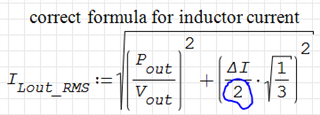
    But let me ask about inductor current. There is a formula in the application report SLUA560C:


    And… this formula seems to be incorrect. Let me explain. According to the pictures you provide, one can easily find that "2" missing in the denumerator. You can briefly check my derivation and make sure.

    I also simulated this situation and LTSpice confirms my rms calculations.

    This looks like a typo and deviation is not high, but still, I think this formula in the DS is incorrect, what do you think?

    Regards,

    Vasiliy

  • Hello,

    If you believe your calculations are correct verifying with LTSPice than as an engineer you can choose to use those results.

    Please note that TI does not support LTSpice.

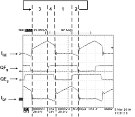
    Please note the waveforms below are actual SR/Secondary winding currents that the application note was based on.

    The equations in the app note and data sheet are based on these wave forms and the calculations were derived as stated above.

    Regards,

  • Hello Mike!

    These waveforms are really representative, thank you.

    Concerning the inductor current, please note that my question was not regarding LTspice so I don't need support with LTspice. I showed these LTspice waveforms to highlight RMS inductor current (I_Lout_rms) calculation error in the datasheet. I think it would be nice to correct this little omission in documents In order not to mislead other people.


    Best regards,

    Vasiliy

  • Hello,

    The calculation you were discussing was the secondary winding RMS current and not the inductor RMS current.  The secondary winding RMS current calculation.   I believe is correct and is based on the wave forms that were discussed.

    Regards,

  • Hello Mike!

    Yes, you are right. My initial question was about secondary rms currents (srms1, srms2, srms3). And your answer is clear to me. Thanks.

    But I also mentioned the inductor current (I_Lout_rms) formula #46.

    This formula, I believe, is incorrect (according to the data you provided and simulation). That is what I am talking about, not the secondary rms.

    Sorry for the confusion, I should have been clearer.

    Best regards,

    Vasiliy

  • Hello,

    Your inductor current RMS equation is for a current double FSFB not a voltage doubler.  The data sheet  uses one inductor which is a voltage double.  Your RMS current equation is for a current doubler.  Which uses two output inductors instead of one.  The data sheet is correct on this one too.

    Regards,

  • Hello,

    More I think about it the current doubler would (Pout/Vout*2).  I dont't think your equation is correct.  Why would you put you divide your inductor ripple current by 2.

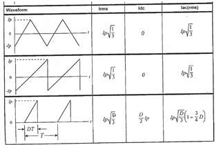
    The RMS current of triangle is Ipk*(1/3)^2  the avearge current would be Ipeak/2.  Look at the RMS current equations that I posted earlier.  They are similar to what Ericson derived years ago.

    Regards,

    Mike

  • Hello, Mike!

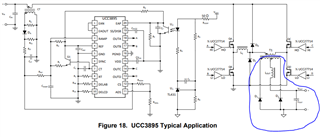
    I think there may be a misunderstanding. I am not sure what you mean by a "voltage doubler" but I am telling about centre-tap full-wave rectifier, the one shown in the figure 18. I am not considering "current doubler" with two inductors!
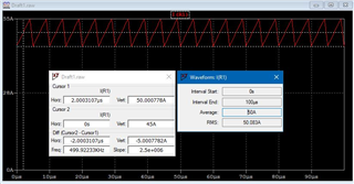
    So the inductor current shold look like this:
    Green wave is the average current, and white wave is the triangle current of the Lout. According to formulas 16, 17 and 18:
    Inductor current will have peak at 55A, mid(avg) 50A, and minimum 45A. So delta_I=55-45=10A. And here it is...
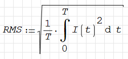
    You can observe the RMS value = 50.083A calculated by LTspice. If you have any doubts about LTspice, you can calculate RMS in a true way. By definition of RMS
    Then it is easy to calculate:
    Or, if you will use RMS current equations that you posted earlier you will end up with the same result much faster:
    So there is nothing wrong with a RMS current equations that you posted earlier. They gave exact same result. 50.083A, but not 50.3A like in formula 53.
    because there must be 2 in the denominator.
    I hope it is more clear now.

    Best regards,

    Vasiliy

  • Hello Vasiliy,

    I don't think your equation is correct.  The average output current through the inductor is 50A.  The RMS current has to be higher the average current.

    Regards,

    Mike

  • Hello, Mike!

    The average output current through the inductor is 50A.  The RMS current has to be higher the average current.

    50.083 > 50 there is no discrepancy here...

    I suspect that I am bothering you a lot and I am sorry but I think there is nothing wrong with my formula. Here is the derivation. Please take a moment and go trough this derivation.. There is nothing complicated and you can easily repeat it if in doubt. I tried hard to make everything clear, so I think it's worth taking a look at least...

    Symbolic integration was accomplished with wolfram alpha

    Best regards,

    Vasiliy

  • Moreover if you assume that this is correct:

    The following equation is must be correct too:

    Irms=1/2*delta_I*sqrt(1/3)

    because delta_I/2=Ip...

    And this means formula 53 missing deltaI/2 and it is incorrect.

  • Hello,

    The equations in the data sheet are estimates.  If it is an over estimate for RMS current that would be O.K.

    I don't think your divide by two in the RMS equation is correct.  The inductor ripple current is always based on D and 1-D.  Why would it divide by 2?

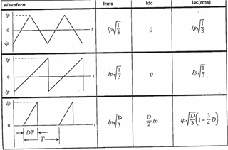
    Here is the RMS current equation for a trapezoid.  You should be able to do it for D and (1-D) then it is the square root of the RMS currents squared and summed. 

    Regards,

  • Hello, Mike

    I don't think your divide by two in the RMS equation is correct.  The inductor ripple current is always based on D and 1-D.  Why would it divide by 2?

    I am assuming 50% duty cycle (0.5*T=ton, 0.5*T=toff) so tatal rms=2*rms1 (refers to my integration calculations). One can show that duty cycle will not affect the rms value while peak(Ip) and minimum(Im) currents are the same for this particular shape (sawtooth). Of course you can redraw my picture for D=80% or 70% or whatever and do both integrals for rms1, and rms2 and then total rms will be total_rms=sqrt(rms1^2+rms2^2) which will give you exact same answer 50.083A. This is just more calculations. That's why I showed a 50% duty cycle case.

    Regards,

    Vasiliy

  • Thankyou for sharing your work.

    Regards,

  • Here is the RMS current equation for a trapezoid.  You should be able to do it for D and (1-D) then it is the square root of the RMS currents squared and summed. 

    This formula is correct. You can derive same as mine result from this formula. It will give you Irms=50.083A for Ip=55A and Im=45A.

    I hope that our discussion did not tire you too much. Perhaps this information will be useful to other people who will refer to the documentation. It would also be great to fix the discussed documentation error in the formula 53 one day.

    Best regards,

    Vasiliy