Hi, everyone. I'm looking for some insight from others with more experience than I have with the TPS61235P. My design is a simple concept: take a 3400mAh Li-ion cell and boost its voltage up to 5.1V, so that it can drive a color 64x64 LED display.
Disclaimer up front: I have never done a boost regulator design, so I took the "TPS61235P Typical Application" from page 1 of the datasheet and went from there.
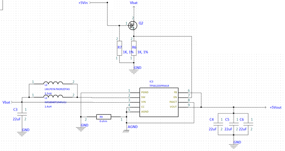
Here are the schematics of the circuit I used in my design:
Notes:
1) L2 is DNP
2) L1 is a Taiyo Yuden NRS8040T1R4NJGJV. Its inductance value is 1.4uH; the datasheet specifies the maximum inductance value as 1.3uH. Its DC current rating is 7A and has a saturation current of 11A and a DC maximum resistance of 9.1 mohms.
3) The Vin capacitor is a 22uF X5R MLCC and has a working voltage of 6.3VDC
4) The output capacitors are the same type as the input capacitor.
5) I currently have AGND and GND tied together at a single point through R9, a zero-ohm resistor. In the redesign, I will eliminate the resistor and replace it with a small trace.
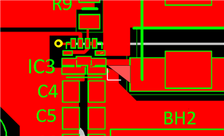
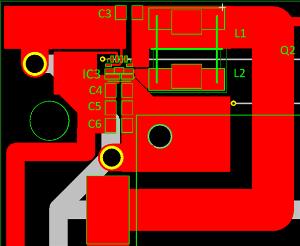
Below, I show the layout I have on my 2-layer board:
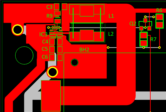
What I am seeing:
Under a no-load condition, I get the expected 5.1V output. However, when I use the output to try to power my LED display (which only requires 350mA at startup), the TPS61235P's output drops from 5.1V to 0V and then goes back to 5.1V at a rate of about 1 cycle per second. It seems that the load is triggering an overload circuit, and then after the TPS61235P resets, it tries again (and fails).
Any help you can give me would be greatly appreciated. Thank you!