This thread has been locked.

If you have a related question, please click the "Ask a related question" button in the top right corner. The newly created question will be automatically linked to this question.

UCC28070: UCC28070

Part Number: UCC28070

Hi,

1)-Is it possible to create Tina file from Webench power designer. For UCC28070 Webench power design is available but for my required ratings I need the Tina file. I need to design 230V Ac-400V Dc for 2Kw power rating.

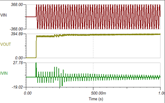
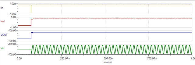
2) In the Tina Model which is present ,why the input current is not sinusoidal?? I am attaching the figure for reference?? How to get a sinusoidal waveform for above required ratings??

  • I'm sorry, but we only have the models that are on TI.com

    I am not sure why the input current is not sinusoidal in the TINA sim.  I will try to understand this but in the meantime, I recommend you proceed with the values you get from the design tool file for your design and enter them in TINA.  Conversely, the PSPICE files are also available and TI for PSPICE is a free download.

  • Hi,

    I have used the values from design tool. I have calculated for for 2kw , 230v ac-400c dc. But i am not obtaining output of 400v and current of 5A. The voltage is just 320v. How to improve this.

    2- In the input current there is a large spike .How to remove that. The current is also not sinusoidal.

    I am attaching the image and file for reference. Could you please check with this.

    UCC28070 AC-DC Tina.TSC

  • Hi Mownika,

    I'm still exploring why the current in non-sinusoidal.  In the meantime, please send me the changes you made for your 2kW design.

    Thank you,

    Ray

  • I have made the changes based on design tool and i have attached the same file above.

  • Hi Mownika,

    Based on what you provided me, I have a few observations:

    VIN appears to be ~400V.  You should change that to your expected VIN. That may also explain why the input current is non-sinusoidal. 

    Your inductors appear to be the same used in the default model.  If the design tool provide you with new values, you will need to change LBOOST in the sub-circuits U6 & U7.

    CSGAIN for U6 & U7 is based on a specific current sense resistor and turns ratio.  33.2Ω and 50 turns is the default resulting in CSGAIN = 33.2/50 = 0.664.  Make sure you adjust this parameter accordingly to your design values.

    If you're not reaching the proper output voltage, you may be limited by the maximum duty cycle you're able to reach with your selected settings.

    Here is a 400V/3kW reference design you may want to look at to compare values: https://www.ti.com/tool/PMP4259

    Here's another for 5kW: https://www.ti.com/tool/PMP4311

    I hope this helps.