This thread has been locked.

If you have a related question, please click the "Ask a related question" button in the top right corner. The newly created question will be automatically linked to this question.

TPS40425: Dual output mode

Part Number: TPS40425

Hi TI expert,

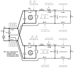
If I configure this device to dual output mode, that means VOUT1 and VOUT2 are independent, below questions:

1. how to measure efficiency of these two rails separately? (how to split input current into 1 and 2)

2. if large load transient is applied to rail 1, can rail 2 output see any cross-talk? what is the noise coupling path and how to reduce?

  • Hi 

    We received your message and will get back to you as soon as possible.

    Best,
    Zhao

  • Hi,

    received, please update if any response.thanks.

  • Hi,

    Yes, for TPS40425, if dual output mode is selected, Vout1 and Vout2 are independent and you can turn on or off the power supply output to determine each efficiency. For example, disable vout2 and measure Vout1*Iout1/Vin*Iin. input current can be measured at input wires and output current can be measured in the output wires.

    For your second question,

    if both Vout1 and Vout2 are powered up, we do see some small amount cross talk between two rails when a large load transient happens on one rail

    I think it is capacitive coupling and there are general rule for PCB layout

    1. reduce the length of Vout1 and Vout2

    2. if possible Isolate Vout1 and Vout2 trace

    3. depends on application Spec, with a slower slew rate and cross talk might be within the spec

    There are also many other techniques on google to reduce the PCB cross coupling:

    Here one scenario of cross talk transient is attached.

    this is for Vout1 have load transient and Vout2 no load.

    Best

    Zhao


  • Hi,

    Thanks for your kind reply.

    But for the second question, are you sure that it is caused by capacitive coupling? Because as you know the amplitude and slew rate of Vout variation is relatively small, it cannot make such compacts on cross-talk.

    Please check below schematic, is it more reasonable that ESL inductive coupling dominates?

    It is easy to check by adding more output capacitors to see  if cross-talk can be reduced or not, which can prove that capactive coulping is correct.

    Otherwise, if cross-talk is influenced by load transient slew rate more, ESL could be the key point.

  • HI,

    Thanks for the reply.

    Yes, you might be right. It should be more due to ESL rather than capacitive coupling.

    if the application can slow down the slew rate, this cross talk can be reduced to an acceptable level. 

    Best,

    Zhao