This thread has been locked.

If you have a related question, please click the "Ask a related question" button in the top right corner. The newly created question will be automatically linked to this question.

TPS62840: TPS62842 minor issues

Part Number: TPS62840

Dear TI Team, 

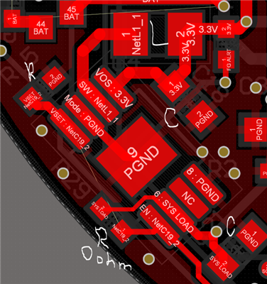
We are using TPS62842 buck converter and our setup is following:

V input = 4.2V

Rset = 52.3k (Desired Vout = 3.3V)

MODE Pin -> Connected to GND ( Low power mode)

EN Pin -> Connected to HIGH (Enable device operation)

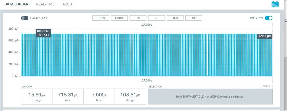
In the device datasheet, it is written that device has 60nA operating quiescent current. When we tested the buck converter with 4.2V input from power supply and zero load, we measured around 15uA current consumption, compared to expected 0.06uA. 

I don't know if it has an effect, but in the datasheet it is written that EN pin has internal 450k pull-down. With 4.2V supply, I = V/R ~9uA. Is it the reason for increased consumption? 

Also wanted to note an observation: we are using recommended inductor that is mentioned in the datasheet. When we change inductor to another 2.2uH model, the consumption fell to 8uA instead of previous 15uA. Is it normal?

  • Hi Rafig,

    I doubt whether you are actually measuring the quiescent current or simply operating input current. We define Quiescent current when the device is not switching but the control circuits are ON. 

    Could you please explain in detail about your measurement setup and probing points?

    Regards,

    Febin

  • Hi Febin,

    Thank you for your message. 

    You can find two screenshots below. 

    This is our PCB. SYSLOAD label means input power, and is connected to power supply(4.2VDC). SYSLOAD is also connected to EN pin. We don't have any load. When disabled EN pin by connecting it to GND, we measured that the output of converter changed from 3.3V to 0V, but the current consumption was the same. 

    We measure current with nRF Power Profiler Kit. Its probes are connected in series with SYSLOAD. And we tie the kit GND to PCB GND. Below is the screenshot of power profiler: 

    In order to verify that measurement is working, we have put a known load to the output of converter, and were able to measure the expected current draw (30mA). 

  • Hi Rafig,

    I will review the above and provide a feedback tomorrow.

    Regards,

    Febin

  • Hi Rafig,

    Please be informed that I am still working on the request. 

    I am planning to verify this on the EVM and I will come back to you by tomorrow.

    Regards,

    Febin

  • Hi Rafig,

    I verified this on the EVM and I can get the Iq, No load operating input current between 60nA-100nA for a 4.2V Vin, 3.3V Vout.

    Please remember that you are measuring a very low current and the setup needs to be highly stable and reliable. Please use very accurate and precise measuring equipment, also it would be better to have a DMM with higher PLC range.

    I would like to share some tips for measuring Iq in general:

    - Connect the power supply and disable the device. Measure the leakage current already in the system/setup using the source meter. This will be your offset and try to reduce this offset by removing bulky capacitors at the input, using shorter cables, suitable connectors and good quality equipment.

    - If possible I suggest to measure Iq on an EVM in your setup and then verify the reliability of the measurement setup.

    - Place the board on a non-conductive surface.

    - Set the DMM to highest PLC range possible. 

    - Additionally, the variations from the power supply and the large integration cycles of the DMM will also give you inaccurate results. So, if you add some bulk capacitors directly at the DMM, it will help reduce Iq.

    - Please remember that if you want to get 60nA exactly, you will have to use the same conditions as specified in the datasheet. When you increase the input voltage and if the input capacitors are more lossy, then this will also increase Iq. 

    - If the Iq is in the range of 60-100nA, then this is acceptable.

    I hope this helps. Please let me know if you have further questions.

    Regards,

    Febin

  • Hi Febin, 

    Thank you very much for verifying it. We will try to follow your tips for the setup and the measurement. I will let you know the results next week. 

  • Hi Rafig,

    Please share your results next week.

    Regards,

    Febin

  • Hi Febin,

    We made a new test setup(new pcb, new converter and etc.), this time we got around 120nA current consumption which very close to 90nA. This measured difference is not significant anymore, so everything looks correct now. Probably there was some hardware problem in previous test which led to different results. Thank you very much for your assistance.