This thread has been locked.

If you have a related question, please click the "Ask a related question" button in the top right corner. The newly created question will be automatically linked to this question.

TPS61021A: loop stability analysis

Part Number: TPS61021A

Hello,

This question is related to : https://e2e.ti.com/support/power-management-group/power-management/f/power-management-forum/1024194/tps61021a-slew-rate-limiter/3806487#3806487

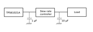
To make sure our design is stable, you proposed to test loop stability in these conditions:
- with 1uF capa, slew rate limiter and 10uF capa on output
- only 1uF capa on output

So we made some measurements for both situations with multiple input voltages (2V, 2.5V and 3V).
I would like to have your advice on the bode plots.

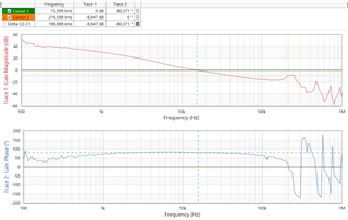
1. 1uF capa, slew rate limiter and 10uF on output

We used a 4Ohms load.
Here is the worst case with 2V input voltage :


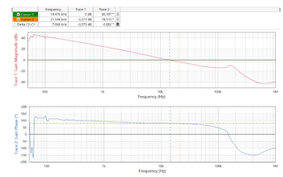
Phase margin is 80° and gain margin 11dB.
The system is stable.

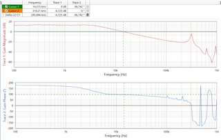
2. only 1uF capa on output

We used a lighter load of 20 Ohms.
Here is the worst case with 2V input voltage :


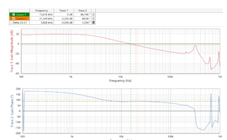
Phase margin is ok : 85° but gain margin is a bit low : around 5dB.
The low gain margin is due to the pic around 300kHz.

Is it something we should worry about or can we safely keep the 1uF capacitor at startup ?

Note : the method used for the measurements is described here : www.omicron-lab.com/.../App_Note_DC_DC_Stability_V3_3.pdf

Thanks for your help
Guillaume


  • Hi Guillaume,

    Good to see you again and thanks for your questions. I see not much difference between your method and mine. For the test results with only 1uF capa on output, the gain margin is low. This could be caused by two reasons:

    1.1uF capacitor capacitance is too low at that DC bias. Or 1uF is not sufficient to keep gain margin enough. You need to add or increase the capacitance;

    2.Input filter. Refer to below application note. Without well design, input filter has something to do with gain margin at high frequency. You need to add a big capacitor at input side to check if the loop is influenced by input network. 

    https://www.ti.com/lit/pdf/snva801

    -Wenhao

  • Hello Wenhao,

    Following your advice we made a few more measurements.
    However none of the 2 options seems to resolve the issue because the peak at 300kHz is always there.

    1. Measurement with 4.7uF output capacitor and 2.5V input voltage :


    2. Measurement with 10uF added at the input and 2V input voltage :


    There seems to be some kind of resonance in the circuit, perhaps between the inductance and the output capacitance.
    What are your thoughts about that ?

    Thank you
    Guillaume

  • Hi Guillaume,

    I am in Holiday until 10.10. Will reply you the week after that. Thanks!

    -Wenhao

  • Hi Guillaume,

    Sorry for delay. I think you should keep the device in PWM so its bode plot is of most meaningful. TPS61021A would enter power save mode in light load. Let me check with design of threshold entering PSM.

    TPS61021A implements valley current COT control and there should be no resonance in gain plot, as inductor has been "cancelled" by valley current sensing.

    -Wenhao

  • Hello Wenhao,

    Thanks for your reply.
    However the reason we are doing these stability analysis is to make sure the TPS61021A will remain stable during startup with a slew-rate controller (ref here https://e2e.ti.com/support/power-management-group/power-management/f/power-management-forum/1024194/tps61021a-slew-rate-limiter/3806487).
    Startup duration is around 1ms and load is always light at that point (we wait a little before enabling the load). So during startup the TPS61021A  mainly charges the 10uF capacitor.

    I think the TPS61021A operates in PFM during this phase.
    Measurements during startup ( yellow is slew rate output, green is TPS61021A output) :


    That's why we made the analysis with light loads for the 1uF only case.

    Thanks
    Guillaume

  • Hi Guillaume,

    Understand. I just checked with design. The device enters PSM when inductor valley current triggers 200mA. This means, if inductor Ip-p is 1.1A, the device stays in power save mode whenever inductor avg current is below 200+1100/2=750mA. For 2Vin to 4.2Vout, it means 320mA load current (90% efficiency).

    Stability:

    The stability in power save mode is always stable, so there is no need to check stability;

    The stability in PWM needs to be checked with only 1uF caps, which needs load to be higher than 320mA;

    Soft-start charge current:

    The typical soft-start time is <100us for your 1uF capacitor, so charge current is around 20mA. Plus your load of 40ohm, the maximum current would not exceed 320mA. 

    This means the device always stays in power save mode during start-up. If there is no possibility of more load current, the device is always stability. However, as you could see during slew rate controller is activating, TPS61021A are seeing more load. Before 10uF is fully on Vout, what current TPS61021A is seeing is 10uF charge current+load current. You may check if it is exceeding 320mA. Thanks!

    -Wenhao

  • Great that really helps. Very good to know that PSM is always stable.

    I have two comments :

    Stability :
    You said "The stability in PWM needs to be checked with only 1uF caps".
    But if we make sure TPS61021A is in PSM during startup (TPS61021A softstart and slew rate controller activation) then we always have 1uF+10uF in PWM mode so no need to check PWM stability with only 1uF. Do you agree ?

    Soft-start :
    Charge current of the 1uF capacitor is much higher than 20mA at some point during TPS61021A softstart. I didn't measure it but given the input voltage drop (100mV on 2 AA), I guess a few hundred mA at the output. Perhaps we need to make sure we are effectively in PSM during all TPS61021A soft start ?

    Guillaume

  • Hi Guillaume,

    Could you please see my reply below?

    1.But if we make sure TPS61021A is in PSM during startup (TPS61021A softstart and slew rate controller activation) then we always have 1uF+10uF in PWM mode so no need to check PWM stability with only 1uF. Do you agree ?

    [WW]Yes and no. If 1uF only exists in PSM, then it is not necessary to check stability;

    Charge current of the 1uF capacitor is much higher than 20mA at some point during TPS61021A softstart. I didn't measure it but given the input voltage drop (100mV on 2 AA), I guess a few hundred mA at the output. Perhaps we need to make sure we are effectively in PSM during all TPS61021A soft start ?

    [WW]You could measure the inductor current. If its valley point stays above 200mA at start-up after Vout>Vin, then it means the device is in PWM when SS. If inductor  valley point is below 200mA, then it means device is in PSM when SS.

    -Wenhao

  • Ok Wenhao, thank you.