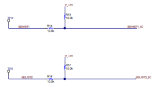
I'm getting ready to use the TPS274160EVM that I received today and in looking through the documentation, the circuitry used to set SEL and SEH on the TPS274160EVM doesn't seem quite right. A screenshot taken from the PDF of the portion in question:

The test points on the left can be jumpered to either GND or V_+5V in order to select which output's current sense signal gets put on CS. This would apply either +5VDC or +2.5VDC to the input pins for SEH and/or SEL (ignoring the effect of the IC's internal pulldown on each pin) -- this seems to be not what is intended (should be +5VDC or GND). I will be removing R13 and R17 before using the TPS274160EVM, since then the jumpers will be able to assert the SEH and SEL pins to the correct levels in order to set which output's current sense signal gets placed on CS. The internal pulldowns have a specification of a minimum of 100kohm, so when driven high by jumper placement, 4.54V gets applied and when driven low by jumper placement, it properly goes down to GND.


