Other Parts Discussed in Thread: PTD08D210W
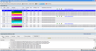
I am using Xilinx's ZC702 board having problem with POWER_GOOD.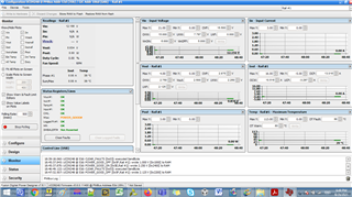
Four Numbers of Rails are not working
This thread has been locked.
If you have a related question, please click the "Ask a related question" button in the top right corner. The newly created question will be automatically linked to this question.
I am using Xilinx's ZC702 board having problem with POWER_GOOD.
Four Numbers of Rails are not working
Hi,
Just to confirm with you.
Do you mean the Vout is regulated but Power Good is not asserted?
And there are four rails and all of them have the same situation?
Dear Derrick Su,
Thanks for your reply.
Vout is not regulated.
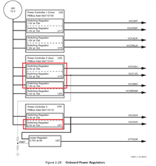
In ZC702 board total 10 Nos of Vout with three UCD9248 Digital PWM Controllers.
4 Nos of Vout are not regulated.
Hi Dave,
But according to your screenshot, it shows Vout is 0.834V and status is OK. So I feel kind of confused.
Otherwise, could you check what's the difference between 4 Nos of Vout are not regulated(does it mean 4 rails?) and 6 Nos of Vout are well regulated?
Like hardware setting, NVM setting, power source for chip, etc...
Dear Derrick Su,
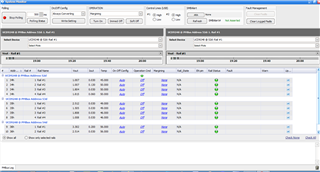
Please find attached screenshot for desired rail voltage & observed rail voltage.
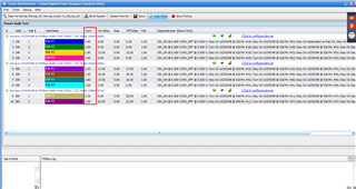
Desired Rail Voltages
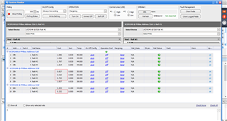
Monitored Rail Voltages.
Hi,
Could output voltage be adjusted through GUI? Suppose to be adjusted by vout command.

Dear Derrick Su,
I tried to reprogram Power Controllers by default XML files (https://support.xilinx.com/s/article/53599?language=en_US) using TI Digital Power Manufacturing Tool but getting problem in mentioned four rail voltages.
In my case I am getting only POWER_GOOD# Status.
Refer Similar Problem given below
e2e.ti.com/.../ucd9248-fusion_mfr_gui-to-program-power-controllers-on-zc702-eval-board-by-xilinx
Hi Dave,
As Matt suggested, could you try to use Fusion Digital Power Designer to bring-up?
"I would suggest to try to bring up the board with Fusion Digital Power Designer instead of the Manufacturing GUI"
Can you provide me with which file to be used in Fusion Digital power for reprogramming Power Controllers?
Can I use given xml files (https://support.xilinx.com/s/article/53599?language=en_US) in Fusion Power Designer Application ?
HI Dave,
I'm not familiar with the xml file you download from xilinx website.
If you communicate with UCD9248 through Fusion Digital Power Designer, you can change the configuration or send the command directly without importing any xml file.
Hi Derrick, I am not able to restore my board. Is there any way to check health of UCD9248 Power Controllers. I would like to identify location of error.
I tried to bring up board with Fusion Digital Power Designer. It didn't solve my problem.
Hi Dave,
I compare the configure file between regulated 1.8V and non-regulated 1.8V.
But can't find something different except the sequencing dependencies. I'm still checking the if it would cause the power-up failure.
Otherwise, do you check the the status of the FLT, PWM, SRE signals from the controller-power stage yet?
Would like to confirm if the rail is trying to regulate or trigger any fault.
It's better to observe the waveforms from start-up.
Hi Dave,
Could you also check the pin10, pin41 & pin50 UCD9248 @ Addr 53d?
According to the turn-on and stay-on dependence of config. code, the device should detect the pin10, pin41 & pin50 for each rail as below.
Rail1

Rail2

Rail3

Rail4

| U21 | Frequencey | Duty | ||
| PWMA | Pin18 | PWM ON | 501kHz | 27% |
| PWMB | Pin4 | PWM OFF | ||
| SRE_A | Pin 17 | High | 3V | |
| SRE_B | Pin 5 | Low | ||
| FF_A | Pin 15 | Low | ||
| FF_B | Pin7 | Low | ||
| Vo_A1 | Pin 21 | 3.3V | ||
| Vo_B1 | Pin 10 | 0V | ||
| U20 | ||||
| PWMA | Pin18 | PWM OFF | ||
| PWMB | Pin4 | PWM ON | 501kHz | 7% |
| SRE_A | Pin 17 | Low | ||
| SRE_B | Pin 5 | High | ||
| FF_A | Pin 15 | Low | ||
| FF_B | Pin7 | Low | ||
| Vo_A1 | Pin 21 | 0.8V | ||
| Vo_B1 | Pin 10 | 1V | ||
| U19 | ||||
| PWMA | Pin18 | PWM OFF | ||
| PWMB | Pin4 | PWM OFF | ||
| SRE_A | Pin 17 | Low | ||
| SRE_B | Pin 5 | Low | ||
| FF_A | Pin 15 | Low | ||
| FF_B | Pin7 | Low | ||
| Vo_A1 | Pin 21 | 0.8V | ||
| Vo_B1 | Pin 10 | 0V | ||
| U18 | ||||
| PWMA | Pin18 | PWM ON | 498kHz | 14% |
| PWMB | Pin4 | PWM ON | 498kHz | 14% |
| SRE_A | Pin 17 | High | 3.3V | |
| SRE_B | Pin 5 | HIgh | 3.3V | |
| FF_A | Pin 15 | Low | ||
| FF_B | Pin7 | Low | ||
| Vo_A1 | Pin 21 | 1.8V | ||
| Vo_B1 | Pin 10 | 1.8V | ||
| U17 | ||||
| PWMA | Pin18 | PWM ON | 498kHz | 8% |
| PWMB | Pin4 | PWM ON | 498kHz | 8% |
| SRE_A | Pin 17 | High | 3.3V | |
| SRE_B | Pin 5 | HIgh | 3.3V | |
| FF_A | Pin 15 | Low | ||
| FF_B | Pin7 | Low | ||
| Vo_A1 | Pin 21 | 1V | ||
| Vo_B1 | Pin 10 | 1V |
Hi Dave,
The PWM signals of four rails are OFF and no any fault occurs. I think it probably ever power up yet.
So you can check the signal of sequencing dependencies as I mentioned earlier.
According to the schematic, three UCS9248 would use the GPIO to control the sequence mutually.
Take U32 as example, the four rails are controlled by Pin 18 & 52 which set the configuration as GPI.
And set pin52 of U33 & pin18 of U34 as GPO to enable the four rails of U32.
Of course, I think you can try to uncheck all the turn-on/stay-on dependencies of U33 to see if it can power on correctly.
U32:


U33:

U34:

Hi Derrick,
Many thanks for your answer, it helped me for getting partial solution.
I have unchecked all the turn-on/stay-on dependencies of U33 & U34.
Now only one Rail of (Rail#2) of U33 (1.5V) is not working.
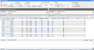
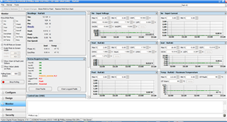
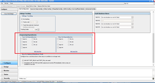
I am not getting PWM Signal on U19's Pin No.4
FLT Pin :Low (Pin No.7)
SRE : Low (Pin No.5)
Hi Dave,
Great. Sounds good.
Could you check the status tab? I would like to know which specific fault is triggered.
Also, when you measure the PWM signal, could you check from soft-start but not just steady-state?
That can help us clarify that if PWM signal is abnormal, it's caused by fault or from begining.
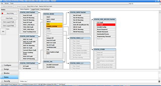
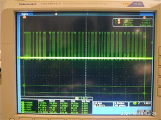
We observed Soft Start PWM Signal after Power Cycle.
Its of 500kHz Freq with 2% Duty for duration of 365us .
Measured at Pin No.4 of U19.
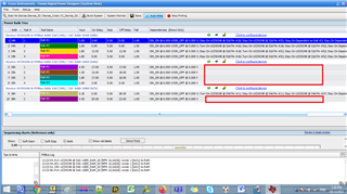
Hi,
It looks like FLT fault but the FLT pin is low(pin7). Could you confirm it again?
The fault from PTD08D210W is active high when it triggers current limit fault.
And the PWM signal is sent out during power-up. So probably the output voltage is trying to rise up.(also you can check the Vout)
But somehow the fault occurs from FLT(PTD08D210W) and then shutdown again.
It seems like the hardware issue since you already uncheck all the turn-on/stay-on dependencies.
And I check the setting of failed rail, nothing different compared to normal rail.


Hi Derrick,
Sorry for Delayed Reply.
Yes,FLT Pin (Pin No.7) of U19 remains Low.
Please find below waveform of Output Voltage and PWM Signals during Startup.
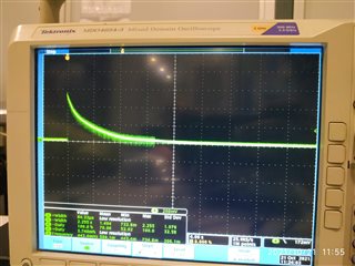
Output Voltage of U19 (Pin No.11)
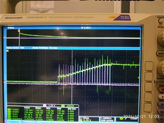
Output Voltage and PWM Signal Measured at U19's Pin No.11 and 4.
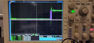
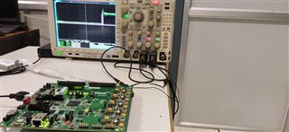
Please suggest.
Hi Dave,
It looks like there is current limit trigger. So the output voltage is limited cannot rise up to target.
Could you check the output impedance or R80 to see if it's normal? Need to find out what's the reason of limiting output voltage.
Or replace a new PTD08D210W. Or swap to see if the symptom follow the failure one.
Also, you can confirm the pin7 of U19 during power-up to check if FLT is asserted.

Hi Dave,
What about replace a new one or swap?
Hi Derrick,
Sorry for delay.
I have replaced U19 with new one.
Now my board is working fine with unchecking dependencies at Address 53
