This thread has been locked.

If you have a related question, please click the "Ask a related question" button in the top right corner. The newly created question will be automatically linked to this question.

TPS23861: Programming I2C slave address

Part Number: TPS23861

Hi,

My customer will use 2x TPS23861. In this case, Programming I2C address isn't required at this moment. (He can use temporary slave address by setting A3 pin).

- Does the connection from AOUT of first device to AIN of second device requires in Figure 50 in datasheet? (Can the pins leave open if he use temporary slave address? )

- Without programming I2C slave address to EEPROM, can customer set the address via initial SLA0 ~~ SLA6 value + A3 PIN?

Regards,
Nagata.

  • Hi Nagata-san,

    I highly recommend they maintain the AOUT to AIN connection from one TPS23861 to the other. This is also how we connect the EVM and want to make sure that customer is able to address each IC when necessary. If customer wants for testing purposes, they can put a resistor to separate the connections and both can be floating; however, i recommend staying similar to what we do on EVM which is known working solution to minimize risk and is replicated on many projects already today.

  • Darwin,

    Thank you very much for your comments.

    Could you please let me know about TPS23861EVM-612? It has a digital isolation (ISO7241) in I2C line. I guess this system cannot support the clock stretch (or some guy say it as clock low hold) which has one of I2C feature at TPS23861 side. Does TPS23861 not need the clock stretch?

    Regards,
    Nagata.

  • Hi Nagata-san,

    Clock stretch is not a requirement for TPS23861. The digital isolation is there to protect any host controller from seeing the high voltage of PoE. In this case for the EVM, it is the MSP430 launchpad or it is your laptop when you evaluate the board using the GUI. Thanks!

  • Darwin,

    Could you please give me your advice for below:

    1. EVM schematic:
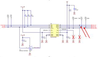
    This is re-confirmation. EVM schematic doesn't have pull-up as arrow shows. Does the pull-ups not need at the line? I guess SCL and SDA line which primary side of ISO7241 has pull-ups. It already send "high" or "low". Then Pull-ups at PSE-SCL and PSE-SDAI doesn't require pull-ups. Is it correct?

    2. Default value of EEPROM for I2C slave address:

    Could you please let me know default value of EEPROM? If default value is 0x20, user can use the value without programming I2C address.

    Regards,
    Nagata.

  • Hi Nagata-san,

    1. Looking at the datasheet of the isolator, it has a push pull outptu stage. So the internal FETs will allow the pull up and pull down of the output signal. So there is no need for pull resistors since it is not open drain output.

    2. For the default I2C address, please see table 10 of the datasheet. On register 11 the default will be 1010,0000.

    Thanks!

  • Darwin,

    Thank you for your supports.

    In this time, customer would like to know if TI has solution for surge at RJ45. Do you have recommend protection IC or circuit for the surge?

    Regards,
    Nagata.

  • Hi Nagata-san,

    Please see below reference design for your reference for lightning surge up to 6kV. Thanks!

    https://www.ti.com/tool/TIDA-01411